40 fe ni phase diagram
Fe-Ni Phase Diagram [2010Cac] The Fe-Ni system:Thermodynamic modeling assisted by atomistic caluculations, G.Cacciamani, A.Dinsdale, M.Palumbo, A.Pasturel, Intermetallics 18 (2010) 1148-1162. Database for FactSage (registration required) Ni Mo Si W Cr Mn wt. % of alloying elements C eutectoid (wt%C) Ni Ti Cr Si Mn W Mo Review Fe-C phase diagram • 2 important points-Eutectoid (B): γ⇒α+Fe 3C-Eutectic (A): L ⇒γ+Fe 3C Fe 3 C (cementite) 1600 1400 1200 1000 800 600 400 0 12 3 4 5 66.7 L γ (austenite) γ+L γ+Fe 3C α+Fe 3C α + γ L+Fe 3C δ (Fe) C o, wt% C 1148°C T(°C ...
The Fe-Ni phase diagram has been constructed by the CALPHAD (CALculation of PHAse Diagram) community , , , and reviewed in the ASM handbooks , . As far as the present authors know, these have been considered "standard" references in all subsequent studies and also adopted in numerous thermodynamic databases.
Fe ni phase diagram
The F-phase has a higher content of Cr and Fe , and hence can lead to the strong depletion of these two elements in the tip of ModA used for IFE calculation, see Fig. 6 (a). This depletion can also have a further influence on the IFE of Ni in ModA. Since Fe and Cr are already strongly depleted, the lack of Ni at the GB is not as pronounced. 4.2 (1) The most reliable Fe - Ni phase diagram in its low-temperature part is the one published in Ref. , which is presented in Fig. 2b. (2) For the first time, the formation of the equilibrium Fe 3 Ni phase in an alloy of Invar composition Fe-32 at.% Ni has been experimentally realized and logically proven. Fe-Ni-P PHASE DIAGRAM AT 6 GPa. D. A. Minin1,2, A. Shatskiy1,2, K. D. Litasov1,2, 1Sobolev Institute of Geology and Mineralogy, SB RAS, 3 Koptyuga Ave, Novosibirsk, 630090, Russia (mindanalex@gmail.com); 2Novosibirsk State University, 2 Pirogova st, Novosi- birsk, 630090, Russia Introduction: The Fe-Ni-P is one of the basic phase diagrams for understanding core formation processes in
Fe ni phase diagram. b t m 0 v 1' Fe-Ni Phase Diagram u. T-r I. Guidstein and R. E. Ogilvie ABSTRACT The CY and y solubility limits in the Fe-Ni phase diagram have been redetermined at temperatures above 500OC. couple and a quench-and-annea technique were used. limits were measured with an electron probe microanalyzer. The phase equilibria were studied with Fig. 1 Fe-Ni-Si isothermal section at 850 °C [2009Zha] 184 Journal of Phase Equilibria and Diffusion Vol. 31 No. 2 2010 Phase Diagram Evaluations: Section II optical and scanning electron metallography, x-ray powder References diffraction, and energy dispersive x-ray analysis/electron probe microanalysis. Fe-ni phase diagram Alpha and gamma solubility limits in iron-nickel phase diagram at high temperatures - quench- and-anneal and diffusion couple techniques and electron probe microanalysis. Document ID. 19650020214. Document Type. Technical Memorandum (TM) Authors. Goldstein, J. I. (NASA Goddard Space Flight Center Greenbelt, MD, United States) Microstructure of Ni 3 Al-Ni (Left) and Ni-Al phase diagram (Right) 6. Shaft As discussed in the previous section, the engine shaft rotation is driven by the turbine, and the ... 6Al-4V alloys, Fe-, and Ni-based superalloys. The common materials would be Cr-Mo-V steels, Inco-718, and Maraging steels (GE1014). The Maraging steel is a very strong ...
In Vol. 12, No. 3, page 301 ("The Fe-Ni (Iron-Nickel) System," by L.J. Swartzendruber, V.R Itkin, and C.B. Alcock), in Table 6 three figures contained incorrectly placed decimal points. In the first line following the subhead "bcc phase," 11 736.4 should be 127 364. In the first line following the subheading "fcc phase," 11 274 ... Publication detail. Home. Rate this publication. Phase diagrams for FE-CR-NI based alloys. Part 1: Phase diagrams for binary and ternary alloys of FE, CR and NI with C and with SI. EU publications. Download Order. In this context, based on the phase diagram published by Cacciamani et al. [16] (Figure 3), the equilibrium cooling of a c-alloy of FCC structure should result, depending on the initial Fe:Ni ... Fe-Ni Phase Diagram. from Dominik Hezel Plus . 2 years ago. Fe and Ni are the two most abundant siderophile elements. The relative, solar abundances of Fe and Ni are at first order about 10:1. Meteoritic metal therefore contains about 90 wt% Fe and 10 wt% Ni. Metal in meteorites occurs as one of the phases: Ni-poor kamacite and Ni-rich taenite.
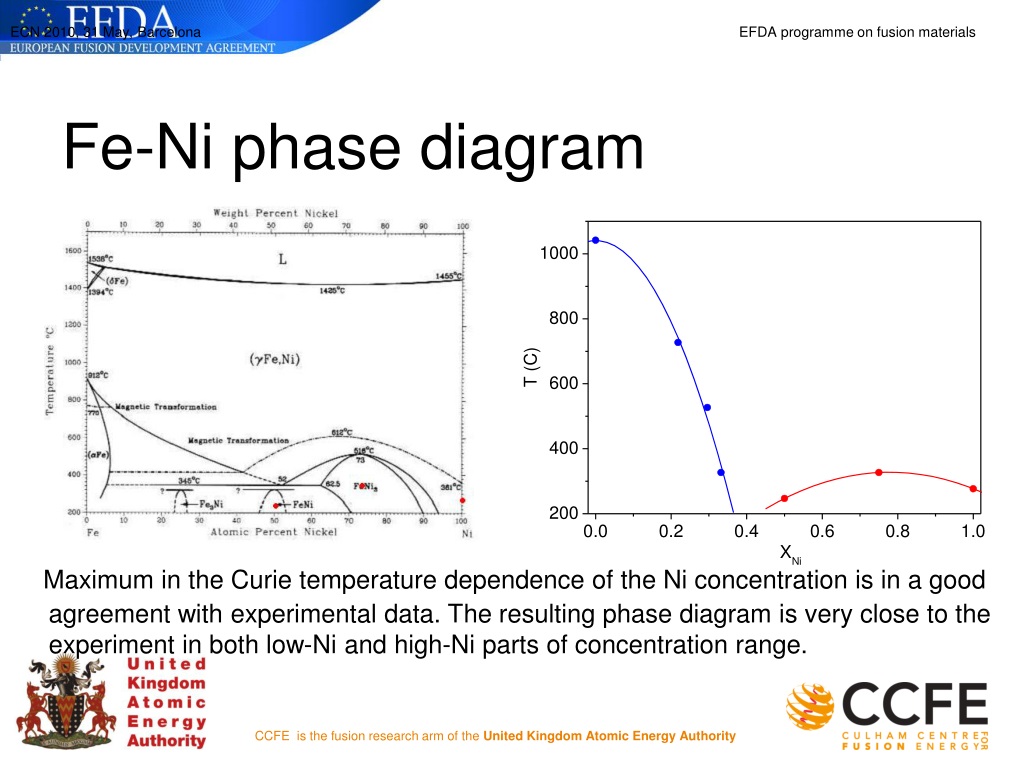
The Fe - Ni phase diagram (with continuous row of solid solutions and presence of extrema on the liquidus and solidus lines) is a diagram of a limiting type. This is confirmed by the range of dissociation of the FeNi 3 intermetallic. The phase diagram has been amended with allowance for the special features of limiting diagrams and for the ... as axes are called phase diagrams. DEF. A phase diagram (or equilibrium diagram) is a diagram with T and composition as axes, showing the equilibrium constitution. The phase diagram of an alloy made of components A and B, for all combinations of T and X B, defines the A-B system. Binary systems have two components, ternary systems three, and so on. A rather basic attempt at animating the FeNi phase diagram - scientifically a little crude courtesy of my very amature animation skills The (gFe,Ni)-phase occupies wide temperature-composition region. There is a minimum on the liquidus and soli-dus curves of the (gFe,Ni) phase. The maximum solubility of Ni in (dFe) and (aFe) is 3.5 and 6.4 at.%, respectively. The low-temperature part of the system was discussed in detail in Ref. [16,17]. FeNi3 forms congruently from the (gFe,Ni ...
2
Ni is Copper structured and crystallizes in the cubic Fm-3m space group. The structure is three-dimensional. Ni is bonded to twelve equivalent Ni atoms to form a mixture of corner, edge, and face-sharing NiNi12 cuboctahedra. All Ni–Ni bond lengths are 2.48 Å.

Pdf Fe Ni Si Iron Nickel Silicon Vijayaraghavan Gonuguntla Academia Edu
The accepted version of the Fe-Ni phase diagram contains a c-phase field extending from pure fcc-Fe to pure fcc-Ni, terminal solid solutions based on the bcc a and d phases of iron, and an intermetallic compound c0-Ni 3Fe with the L1 2 structure [1,2]. In meteorite spec-

The Fe Ni Iron Nickel System
7.1. Al-Fe~Ni PHASE DIAGRAM This phase diagram can be used for the analysis of the phase composition of an 8001 alloy (Table 7.1) that contains only nickel and iron as the alloying elements. This phase diagram is also necessary for the analysis of more complex systems. In the Al-Fe-Ni ternary system, the AlsFe, AlsNi, and AIQECNI phases are
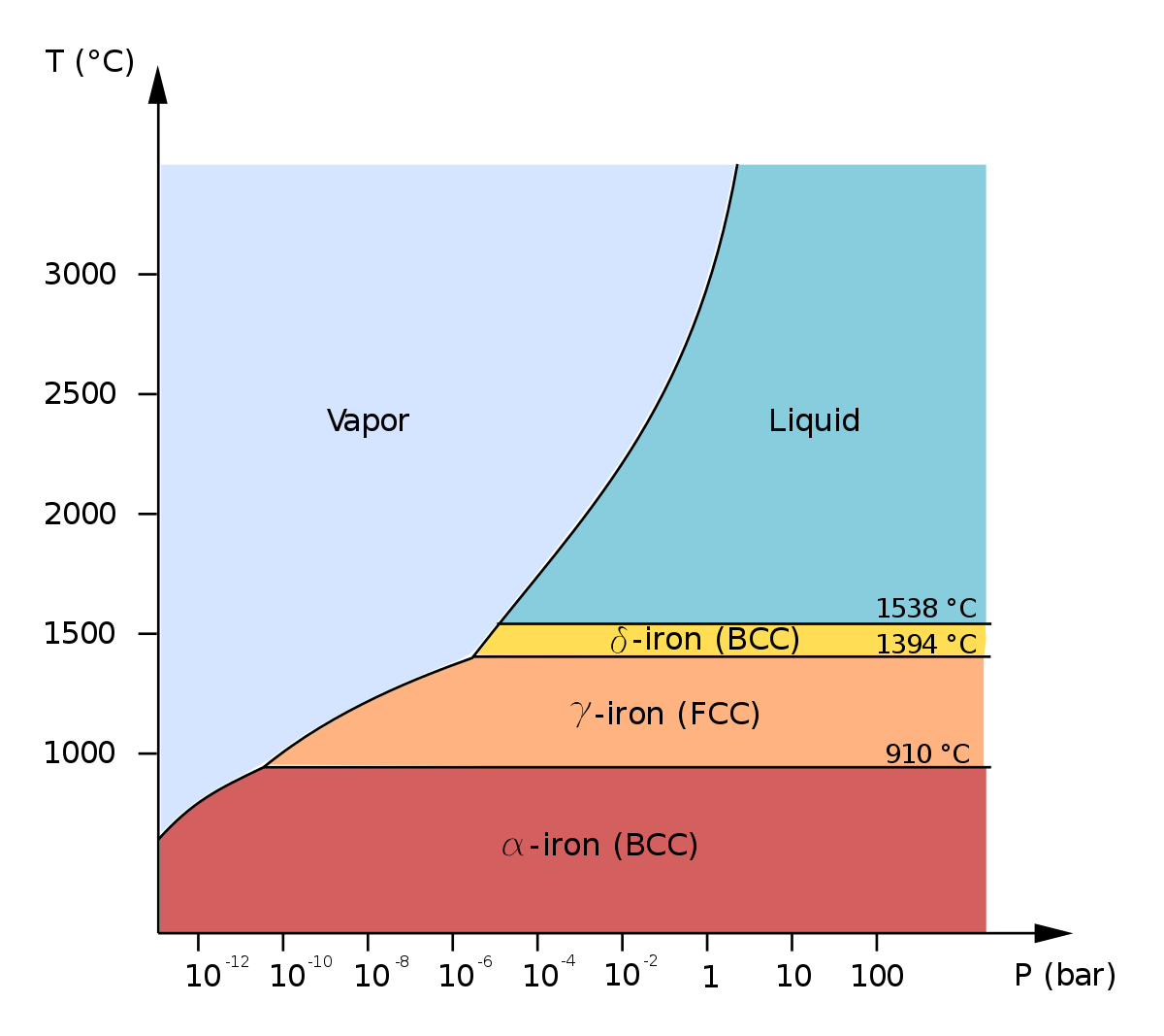
Allotropes Of Iron Wikipedia
Calculated phase diagram of Fe-Ni-O in air at 1 atm. Dashed line from [5], solid line this work. Fig. 20. Calculated and experimental [49] degree of inversion in NiFe2 O4 . Dashed line from [5], solid line this work. Fig. 24.

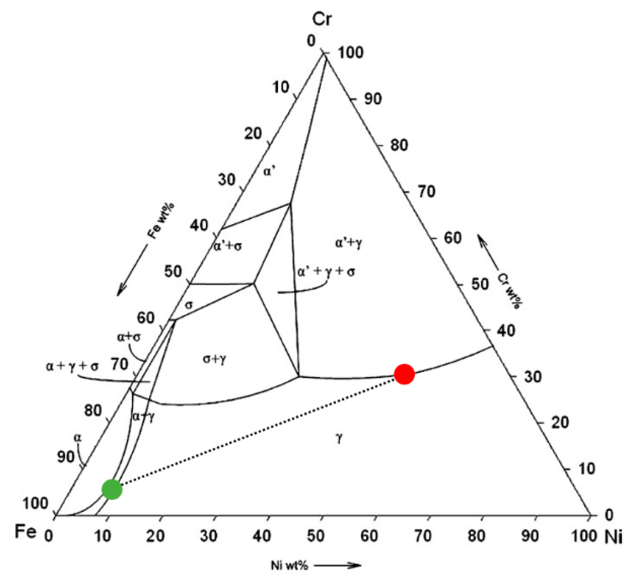
Fig 3 Ni Cr Fe Ternary Equilibrium Phase Diagram At 800 C And Ni Cr Fe Alloys And The Target Alloys Blue Colored Area
Calculated Cr-Fe-Ni phase diagram at 1075K assessed by 1999Mie Ag 100 800 80 (Ag) OXO c9 (CAg) 40 coe (Cu) 60 20 O Cu6Sn5 Sn cu3Sn 20 40 80 100 cu Mass 0/0 cu Zn-Mg-Al-Y First Melting (solidus) projection, mole fraction Yttrium = 0.05 a ± Al,y Tau ± Al,y ± ALMAY Al*' fcc d = Tau Al.MgY fcc Mg mole fractions /(Zn.Mg.A/) Atomie GaA128 Call turn

Quantitative Elaboration Of The Defect Structure Of Iron Doped Nickel Oxide Ni 0 955 Fe 0 045 1 D O By In Situ X Ray Absorption Spectroscopy Physical Chemistry Chemical Physics Rsc Publishing Doi 10 1039 B103884m
The low-temperature Fe-Ni phase diagram was assessed experimentally by investigating Fe-Ni regions of meteorites using high resolution analytical electron microscopy techniques. The present phase diagram differs from the available experimental phase diagram based on observations of meteorite structure, but it is consistent with the available theoretical diagram in that α/Ni3Fe equilibrium was ...

Electroplated Fe Co Ni Films Prepared From Deep Eutectic Solvent Based Plating Baths Aip Advances Vol 6 No 5
This A-Cr phase diagram is shown in Fig. 6 where A = Mn + Fe + Co + Ni in the Cr 26 Mn 20 Fe 20 Co 20 Ni 14 alloy. Three distinct domains exist in the phase diagram: a single-phase fcc region at low Cr concentrations, a single-phase σ domain at high Cr concentrations and a two-phase fcc + σ region in between.
2
The peak at 22.40° corresponds to (420) reflections of fe 2 p. based on the binary phase diagram of cu-p system, p takes the form of cu 3 p in cu-9p alloys. with the addition of fe into cu-p melt, p would tend to react with fe to form the corresponding fe-p compounds, which could be attributed to the relative stronger metallicity than.
2
Fe-Ni is a key system for different technologically relevant materials such as invar alloys, permalloys, inconel alloys, etc. From a fundamental point of view it is interesting for the peculiar interplay between chemical and magnetic ordering phenomena. Fe-Ni phase diagram has been studied for more than a century.

Some Discussion Topics On The Representation Of The Equilibrium Fe Ni Phase Diagram And On The Nature Of The Invar Effect Iopscience
English: The binary phase diagram of Fe-Ni, focusing the area of temperature from 400 °C to 1600 °C and Ni mass percentage from 0 % to 50 %. Meanings of the symbols in the diagram are as follows: The diagram was drawn by the uploader based on the following reference: ステンレス協会(編). 1995.『ステンレス鋼便覧』第3版.
Collection Of Phase Diagrams
g +Fe 3 C a ferrite a +Fe 3 C L+Fe 3 C d (Fe) Carbon concentration, wt.% C Eutectic Eutectoid 0.77 4.30 727°C 1148°C T(°C) Steels <1.4wt%C Cast Irons 3-4.5 tic • Ferrous alloys: iron is the prime constituent • Ferrous alloys are relatively inexpensive and extremely versatile • Thus these alloys are wide spread engineering materials

Fe Ni Phase Diagram 16 Download Scientific Diagram
May 17, 2021 · The Fe, Co, and Ni K-edge XANES data were recorded in a fluorescence mode. Fe, Co, and Ni foils and Fe 2 O 3, Co 2 O 3, and NiO were used as …
2
Fe-Ni-Al phase diagram in ALNI type permanent magnets related area Abstract: With 36 alloys selected from indications provided first by differential thermal analysis and by other methods of analysis and physical measurements, it has been possible to specify accurately the Fe-Ni-Al ternary diagram. This research enabled us to : 1. Give a better ...

The Equilibrium Phase Diagram 34 35 For Fe Ni System The Two Download Scientific Diagram
Phase diagrams at intermediate temperatures are critical both for alloy design and for improving the reliability of thermodynamic databases. There is a significant shortage of experimental data for phase diagrams at the intermediate temperatures which are defined as around half of the homologous melting point (in Kelvin). The goal of this study is to test a novel dual-anneal diffusion multiple ...
2
The L12-Ni3Fe compound has the largest negative formation energy, which is consistent with the experimental Fe-Ni phase diagram. The L10-FeNi compound has also been observed experimentally in meteorite samples as a metastable phase. It is suggested here that the C11f compounds could also form in Fe-Ni alloys at low temperatures.

Fe Ni Phase Diagram 5 8 Download Scientific Diagram
Al-Fe~ Ni PHASE DIAGRAM This phase diagram can be used for the an al ysis of the phase composition of an 8001 al loy (Table 7.1) that contains only ni ckel and iron as the al loying elements. This phase diagram is al so necessary for the an al ysis of more complex systems. In the Al-Fe-Ni ternary system, the Al sFe, Al s Ni, and AIQEC NI phase ...
61 Local Melting In Al Embedded With Tini Powder Induced By Microarea Self Propagating High Temperature Synthesis
Fe is Tungsten structured and crystallizes in the cubic Im-3m space group. The structure is three-dimensional. Fe is bonded in a distorted body-centered cubic geometry to eight equivalent Fe atoms. All Fe–Fe bond lengths are 2.47 Å.
Ppt M Odelling Of Phase Diagrams Of Iron Alloys Powerpoint Presentation Id 9608845
(1) In 1907, Treitschke and Tammann found that the 𝜎 phase in the Fe-Cr binary system was an intermetallic compound of 30 wt.% Cr~50 wt.% Cr . (2) In 1927, Bain and Griffiths observed the successful 𝜎 phase in the Fe-Cr-Ni ternary system.

Pauling File
金属やセラミックスの状態図、エンリンガム図などの情報を提供しています。 一部、不確かなものもありますので、自己 ...

Influence Of Alloying Elements On Steel Microstructure Total Materia Article
The Fe-Ni-W-C phase diagrama has been assessed by using thermodynamic methods. The assessment procedure involves the use of phenomenological models for the Gibbs energy of the various phases.
2
Fe-Ni-P PHASE DIAGRAM AT 6 GPa. D. A. Minin1,2, A. Shatskiy1,2, K. D. Litasov1,2, 1Sobolev Institute of Geology and Mineralogy, SB RAS, 3 Koptyuga Ave, Novosibirsk, 630090, Russia (mindanalex@gmail.com); 2Novosibirsk State University, 2 Pirogova st, Novosi- birsk, 630090, Russia Introduction: The Fe-Ni-P is one of the basic phase diagrams for understanding core formation processes in

Figure 12 Evolution Of Microstructure And Residual Stress Under Various Vibration Modes In 304 Stainless Steel Welds
(1) The most reliable Fe - Ni phase diagram in its low-temperature part is the one published in Ref. , which is presented in Fig. 2b. (2) For the first time, the formation of the equilibrium Fe 3 Ni phase in an alloy of Invar composition Fe-32 at.% Ni has been experimentally realized and logically proven.

Thermodynamic Phase Predictions In High Entropy Alloys Advanced Materials Research Group Of Prof B S Murty
The F-phase has a higher content of Cr and Fe , and hence can lead to the strong depletion of these two elements in the tip of ModA used for IFE calculation, see Fig. 6 (a). This depletion can also have a further influence on the IFE of Ni in ModA. Since Fe and Cr are already strongly depleted, the lack of Ni at the GB is not as pronounced. 4.2
Figure F42 Phase Diagram For The Fe Ni S O System At 300 C And 2 Kbar Phase Boundaries Of Fe Phases Are Marked By Thick Lines Those Of Ni Phases And Ni Fe Alloys Are Thin

C Fe Ni Phase Diagram Pdf
.png)
Fe Ni B 1000 K Japan Atomic Energy Agency
2

Catalytic Nucleation Of A Meta St Preview Related Info Mendeley
Ternary Phase Diagram Overview
1

The Fe Ni Phase Diagram From A Literature 26 Download Scientific Diagram
Metals Free Full Text The Influence Of The Post Weld Heat Treatment On The Microstructure Of Inconel 625 Carbon Steel Bimetal Joint Obtained By Explosive Welding Html

File Meteoric Iron Phase Diagram Taenite Kamacite Svg Wikipedia

Ni Laboratory
2

Part Of The Phase Diagram Of Fe Ni Co Download Scientific Diagram

Scielo Brasil Experimental Evaluation Of 300 ºc Section Of Cu In Ni Phase Diagram Hardness And Electrical Conductivity Of Selected Alloy Experimental Evaluation Of 300 ºc Section Of Cu In Ni Phase Diagram Hardness

Pdf Phase Equilibria And Phase Transformations In The Ti Rich Corner Of The Fe Ni Ti System Semantic Scholar

Figure 4 Precipitation Of Phase Using General Diffusion Equation With Comparison To Vitek Diffusion Model In Dissimilar Stainless Steels

Megfelelo Meredek Koncert Fe Ni Parkwoodinfra Com
0 Response to "40 fe ni phase diagram"
Post a Comment