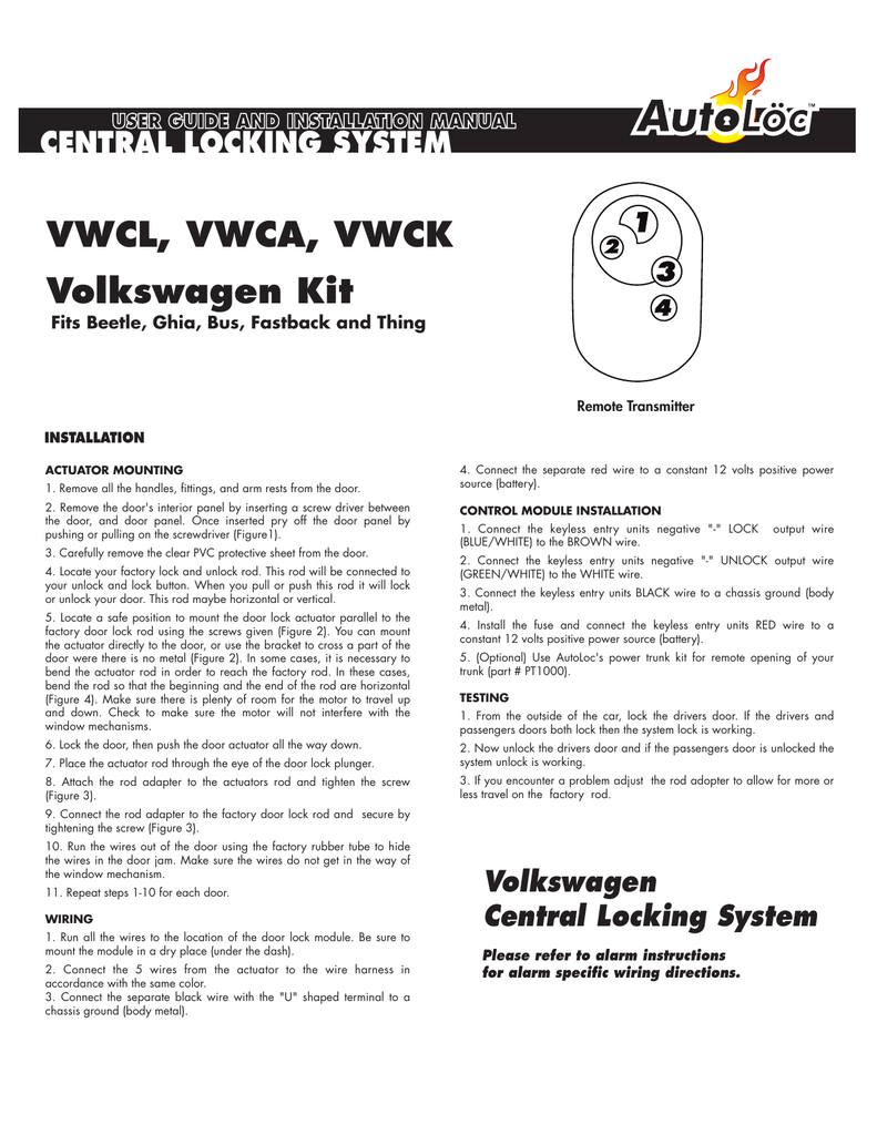
40 shaved door handle kit wiring diagram
60 lb SHAVED DOOR HANDLE KIT 8. Slide the other sleeve over the opposite end of the cable, and run the cable through door loc ... Go back under the dash and connect the power leads according to the wiring diagram 14. After all of the connections are made, take the remote transmitters and pop those loc NOTE: THE LOCK AND UNLOCK BUTTONS CONTROL ... Wiring the Enzor EZ-400 Remote Door Popper KitIn this video I explain in more detail the wiring of the Enzor EZ-400 Remote Door Popper kit.Please download th...
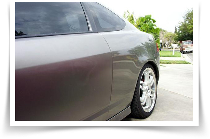
Shaved Door Handles Introduction: In keeping with the "custom rod" theme of my car, I wanted to further smooth off the body lines by eliminating the outside door handles. 90% of the time, my car is parked with the windows down. ... I followed the wiring diagram supplied with the kit. But, basically you will want to wire
Shaved door handle kit wiring diagram
SHAVE DOOR HANDLE SYSTEMS ... Autoloc Shaved Door Kits set the standard for shaved doors done right, ... receivers wiring diagram for.5 pages SHAVED DOOR HANDLE SYSTEM ... Install the smaller screw and washer on the solenoids rear terminal. Remove door's ... DIAGRAM 1: Remote Keyless Entry Unit.4 pages now following wiring diagram make all connections, running wires to doors through factory holes if possible. 7. 10 guage is best, but if your going a short distance, like a few feet, then 12 gauge will do. 8. for door poppers find a location that they can contact door. using their bracket as a template mark three holes needed.
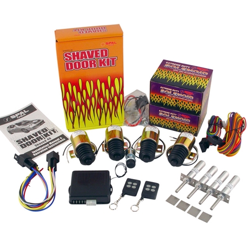
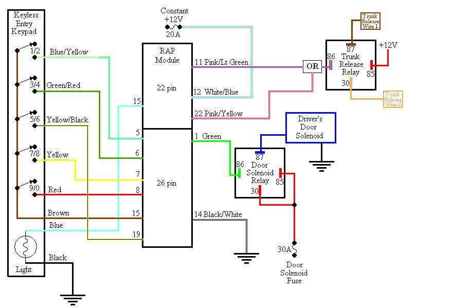
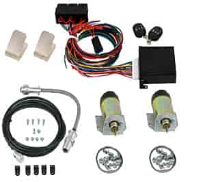
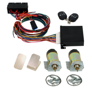
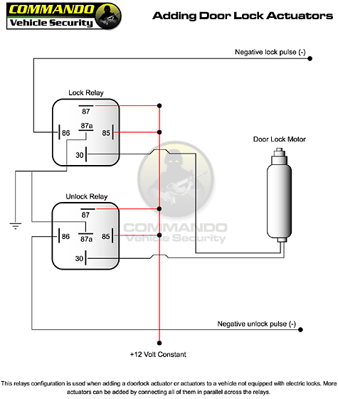
Shaved door handle kit wiring diagram. Autoloc Shaved Door Kits set the standard for shaved doors done right, and your kit will provide you with years of flawless operation, however the kit must be installed properly. Follow the guidelines below and all instructions on the following pages closely. PART # PROTECTION AUTSL35 30 Amp Fuse AUTSL50 40/50 Amp CB AUTSL75/100 60/70 Amp CB Ints allation Instructions for SPAL Shaved Door Handle Kit Shaved-40 This kit is designed to operate up to seven functions via the four-button remote control. Channels 1 and 2 are Positive outputs used to open your drivers and passenger doors. Channels 3 th ro ug7 a elniv p s cb dw k, r, elasc o nt riup w dh ( x ) y. (See Page 7) SHAVE DOOR HANDLE SYSTEMS ... Autoloc Shaved Door Kits set the standard for shaved doors done right, and your kit will provide you ... Safety relay wiring ( THIS DIAGRAM WILL PROHIBIT THE SOLENOIDS FROM OPERATING ANYTIME THE KEY IS IN THE ON POSITION ) Pole 85 - connects to ground I recently bought a 1960 Corvair with shaved door handles and I bought a Protocol PPP35K Shaved Door Handle Kit with the solenoids, relays, etc. The solenoid wiring and installation in the doors seems very straightforward, but I am having trouble with just having a schematic and no step-by-step instructions (I'm not great with electrical wiring ).
PLEASE NOTE: The wiring to the doors on this kit is 14 GAUGE and made to work efficiently with AVS shaved door motors. We recommend that you DO NOT use this kit with SOLENOIDS as they require more amperage than this kit can handle. Shaved Door Handle Kit Wiring Diagram. Print the wiring diagram off and use highlighters to be able to trace the routine. When you use your finger or even the actual circuit together with your eyes, it is easy to mistrace the circuit. One trick that We use is to printing exactly the same wiring picture off twice. UNIVERSAL BOLT-ON SHAVED DOOR KIT USER GUIDE AND INSTALLATION MANUAL † Wiring Diagram 1 & 2 are for Bracket Only Version † Wiring Diagram 3 is for the Kit with Alarm System (SVBCA) † Wiring Diagram 4 is for the Kit with Remote (SVBCR8) USER GUIDE AND INSTALLATION MANUAL 1. Mount Actuators to the Bracket 2. Mount Actuators to the Vehicle 3. (See Figure 2) Run cable through door avoiding all moving parts to ... Safety relay wiring ( THIS DIAGRAM WILL PROHIBIT THE SOLENOIDS FROM OPERATING ANYTIME ...4 pages
How to insatll door poppers scottysdetailing. Shaved door handle kit wiring diagram. Go back under the dash and connect the power leads according to the wiring diagram 14. Wiring diagrams 1 2 tech support hotline. Central locking system cl2000 2 door standard cl4000 4 door standard ck2000 2 door with remote. E u l b n w o r b purple e t i h w n ... Designed to safely integrate with OEM wiring these kits feature a waterproof 10/40 Amp relay along with printed wires which aid in installation. Kits are available with or without thermo-switch. Kits with thermo-swith feature a 3/8. SPAL Shaved Door Handle Kit Shaved This kit is designed to operate two or more functions. This is the second part of the videos showing how I installed the remote shaved door handles poppers on my 1993 Chevy S10 pickup.The first video shows how I ... SPAL Shaved Door Handle Kit Shaved This kit is designed to Please refer to the diagrams on page 7 of this instruction manual for positive, negative, and.Contents of Shaved Door Kit: (1) Driver side bolt-on bracket (1) Passenger side bolt-on bracket the actuator to the bracket. Remove the clip that holds the wiring to the door and push it through.
Static Summitracing Com
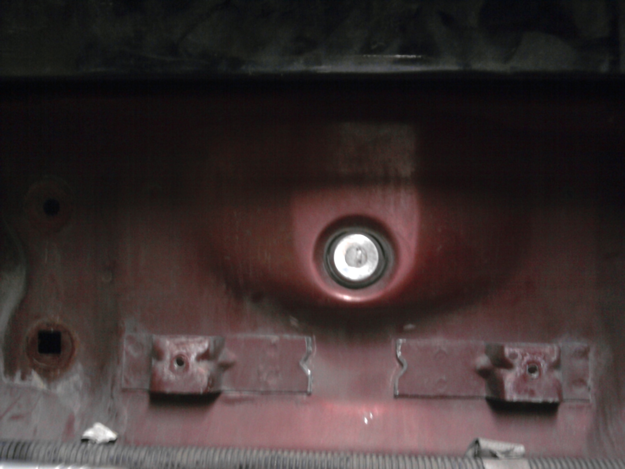
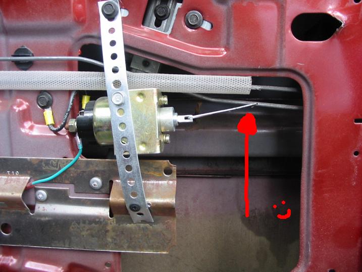
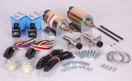
Shaved door popper kits are a sweet way to open your door with shaved door handles. A matter of fact the only other way to open your door would be with a manual pull cable or to simply open your window and use the interior door handle to open your door.

Avs Shaved Door Relay Wiring Harness Plug N Play Avs
SPAL Shaved Door Handle Kit Shaved-DX. This kit is designed to operate ... Please refer to the diagrams on page 7 of this instruction manual for positive,.6 pages

45 Lb Shaved Handle Door Popper Kit With 2 Remotes Youtube
COM SHAVE DOOR HANDLE SYSTEMS SVPRO3 SVPROA3 SVPRO5 SVPROA5 SVPRO7 ... MANUAL WIRING DIAGRAMS SOLENOID INSTALLATION ALARM KITS SVPROA3, SVPROA5, SVPROA7 1.
Keyless Entry Shaved Door Handle Backup Third Generation F Body Message Boards
Contents of Shaved Door Kit: (1) Driver side bolt-on bracket (1) Passenger side bolt-on bracket ... receivers wiring diagram for all other wire connections. IMPORTANT! E U L B / N W O R B PURPLE E T I H W / N E E R G ... BOLT-ON SHAVE DOOR HANDLE KIT WWW.AUTOLOC.COM USER GUIDE AND INSTALLATION MANUAL AUTOLOC DOORS CAR DOORS.
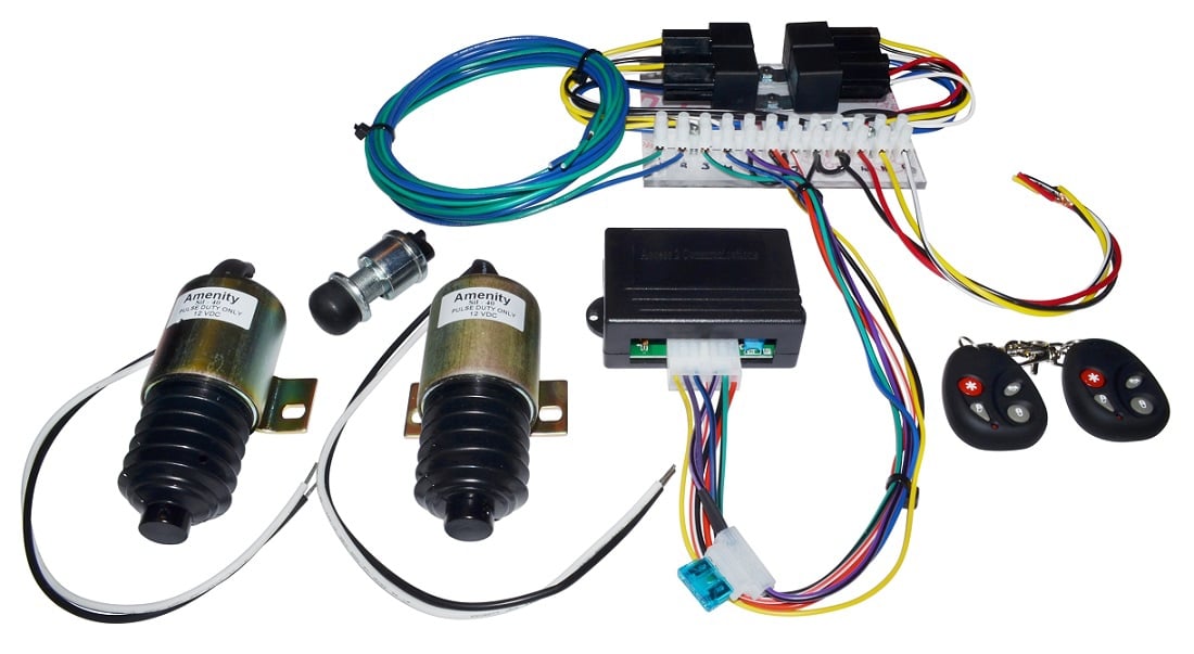
Jaycorp Technologies Spal Amenity Shaved Door Handle Kit
Shaved Door Handle Kit Wiring Diagram. LINEAR ACTUATOR KIT INSTALL DOOR HANDLE AND BEZEL. 2. DIAGRAM MAKE ALL CONNECTIONS, RUNNING WIRES TO DOORS THROUGH. With the trim panel removed, reinstall the door handle and operate the lock. back under the dash and connect the power leads according to the wiring diagram. door latch.
Jaycorp Technologies Spal Amenity 4 Door High Power Shaved Door Handle Kit W Poppers
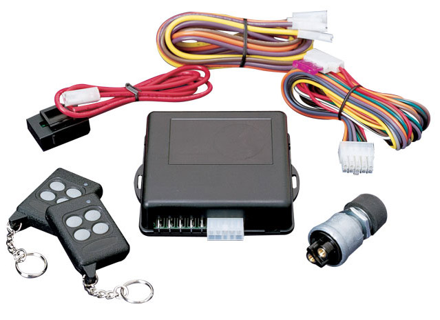
Installing the shaved door handle kit is fairly straight forward. Begin by mounting the control module. The control module must be mounted away from any moisture, preferably under the dash tie strapped to a wiring harness. Once the module is mounted, you will need to run your channel wires to each door. You will use the 7 channel control module ...

94001 Manual Bear Claw Latch Electric Life Power Window Systems Accessories
now following wiring diagram make all connections, running wires to doors through factory holes if possible. 7. 10 guage is best, but if your going a short distance, like a few feet, then 12 gauge will do. 8. for door poppers find a location that they can contact door. using their bracket as a template mark three holes needed.
Chevy Parts Door Latch Kit Emergency Manual Exterior Shaved Door Handle
SHAVED DOOR HANDLE SYSTEM ... Install the smaller screw and washer on the solenoids rear terminal. Remove door's ... DIAGRAM 1: Remote Keyless Entry Unit.4 pages
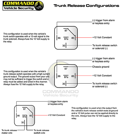
Technical Wiring Diagrams Trunk Release Wiring Diagram For Car Alarm Install
SHAVE DOOR HANDLE SYSTEMS ... Autoloc Shaved Door Kits set the standard for shaved doors done right, ... receivers wiring diagram for.5 pages

Avs Shaved Door Kit With Remote Control System Wiring Harness
Shaved Door Handles And The Poper Kit Third Generation F Body Message Boards
Shaved Door Handles Archives Roadkill Customs
Multircu7rx 7 Channel Control Module User Manual Users Manual Spal Usa
Keyless Entry Shaved Door Handle Backup Third Generation F Body Message Boards

Speedway Tech Talk Shaved Door Kit Youtube
Electric Life 99800 Shaved Door Handle Kit Two 60lb Solenoids Jegs High Performance

Shaved Door Popper Kits How They Work Tips And Installation Techniques X2 Industries
Shaved Doors Handles Ford Truck Enthusiasts Forums

Accessories Installation Products 1 Edit Manualzz
Shaved Door Kits By Scissor Doors Inc Scissor Doors Inc

Shaved Door Kits And Accessories Autoloc Com

Avs Shaved Door Kit For Most 94 Gm Avs

Autoloc Sverkd Emergency Manual Pull Cable Release Kit Shaved Door Poppers Sedan Johnnylawmotors Com
Shaved Door Handle Kits Electrical Part Types Super Bee Truck Accessories
Shaved Door Handle Kit

Installation Manual Operation Shaved Installation Manual Operation Instructions Installation Instructions For Spal Shaved Door Handle Kit

Amazon Com Spal Amenity 40lb Shaved Door Handle Kit With Poppers Automotive
Power Door Lock Kit With Remote And Alarm Installation Instructions Manualzz

8 Function 50 Lbs Remote Shaved Door Popper Kit Autoloc Com
Carid Com

Spal Shaved 40 Basic Shaved Door Handle Remote Entry Kit
Technical Wiring Diagrams

100lb Shaved Door Handle Kit 2 Door Popper Solenoid Street Rat Hot Rod Car Truck For Sale Online Ebay

Shave Door Handle Emergency Release Kit Johnnylawmotors Com

Emergency Release Cable For Shaved Door Kit Door Popper Buy Online In Grenada At Grenada Desertcart Com Productid 7424619
Shaved Door Handles Vintage Mustang Forums

Shaved Door Handles The Cheap Way 7 Steps With Pictures Instructables
Shaved Door Handle Kit With Solenoids

Shaved Door Handle Kit 2 Doors Popper Solenoid Street Rat Hot Rod Car Truck 85lb 54 64 Picclick
Rsrx Remote Controller Receiver User Manual Users Manual Spal Usa
0 Response to "40 shaved door handle kit wiring diagram"
Post a Comment