42 4 wire transmitter wiring diagram
All Installation Types (Integral, 4-Wire, and 9-Wire) Safety messages Safety messages are provided throughout this manual to protect personnel and equipment. Read each safety message carefully ... For wiring between the transmitter and sensor, verify the maximum cable 5:47HowtoConnecta4-20mATransmitter, #DifferentTypesof4-20mATransmitterWiring, #TheFundamentalsof4 ...30 May 2020 · Uploaded by Engineering Concepts
In a 4-20mA loop, 4mA represents the low end of the measurement range and 20mA represents the high end. The voltage specification for most transmitters comes in a range. For example if the voltage of a 2 - wire transmitter is specified as 15 to 24VDC, the lower voltage is the minimum voltage necessary to guarantee proper transmitter operation.
4 wire transmitter wiring diagram
Example 4-20mA thermistor transmitter wiring diagram. So when the ROI-XMA Thermistor transmitter is used with the ROI-USB current measurement A-D, the PC can be used to measure a Thermistor with higher precision than a direct measurement system. The 4-20mA transmitter gain can be adjusted. This can minimize the span of the temperature sensor range. The system is called balanced, because the signal on one wire is ideally the exact opposite of the signal on the second wire. In other words, if one wire is transmitting a high, the other wire will be transmitting a low, and vice versa. See Figure 2. Figure 2. The signals on the 2 wires of a balanced system are ideally opposite. 3 Wire Pressure Transmitter Wiring Diagram. Pressure transducers installation and use 3 wire 4 20ma transmitter wiring technology in sensors electrical connections guide ma types 2 china low range sensor rsinstruments to 20 cur loop output signal 0 5v piezoresistive silicon.
4 wire transmitter wiring diagram. This is the 4 Wire Pressure Transducer Wiring Diagram. 4 Wire Transmitter of a graphic I get from the Pressure Transducer Wiring Diagram package. You can save this photographic file to your personal device. Please right click on the image and save the photo. We also have some more images associated to Pressure Transducer Wiring Diagram, please see the picture gallery below, click one of the ... 3 Wire Transmitter Wiring Diagram. By Admin | December 3, 2017. 0 Comment. 3 wire input isolation for analog outputs precision hub archives ti e2e support forums facebook transmitter dc4 20ma detachable rail type 4 cur signal isolator two transmitters three pressure vacuum test measure inspect keliaukim kartu lt 20 ma wiring types 2 ... 4:48But, is it a 2-wire or a 4-wire transmitter? The actual wiring connection between the transmitter and the ...25 May 2020 · Uploaded by RealPars Tel 248-295-0880 Fax 248-624-9234 sales@acromag.com www.acromag.com 30765 Wixom Rd, Wixom, MI 48393 USA INTRODUCTION TO THE TWO-WIRE TRANSMITTER AND THE 4-20MA CURRENT LOOP 6 3. Transmitter: This is the device used to transmit data from a sensor over the two-wire current loop. There can be only one Transmitter output in any
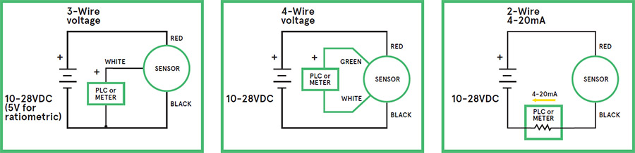
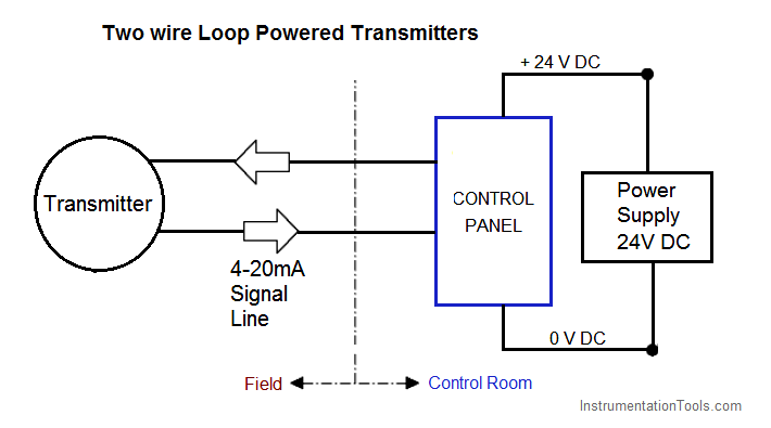
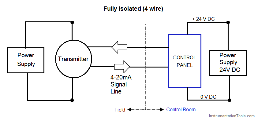
Cables with more conductors will require larger electrical conduit to fit in to, and all field wiring panels will have to contain more terminal blocks to marshal the additional conductors. If no suitable electrical power source exists at the transmitter location, though, a 4-wire cable is necessary to service a 4-wire transmitter. Diagram 2, 3, 4 - wire transmitter working principle and related problems.Two-wire system, three-wire system, four-wire system, refers to the output of a variety of analog dc current signal transmitter, its working principle and structure of the difference, rather than just refers to the transmitter wiring form. So the first thing that came out was a four-wire transmitter;In other words, two ... Transmitter 6: CH6 (+) Terminal with Terminal (14) on the Card (-) Terminal with Terminal (15) on the Card. for the schematic wiring diagram its in the attachments. so, I would like to know if I can use 2-wire 4-20ma in the 8 channels or only in the first 4 channels 4-20 mA Transmitter Wiring. Several transmitter wiring options exist. The design of the associated control panel dictates which option should be used. These wiring options include: Current source transmitter, non isolated (3 wire) Current sink transmitter, non isolated (3 wire) Fully isolated (4 wire) Two wire loop powered transmitters
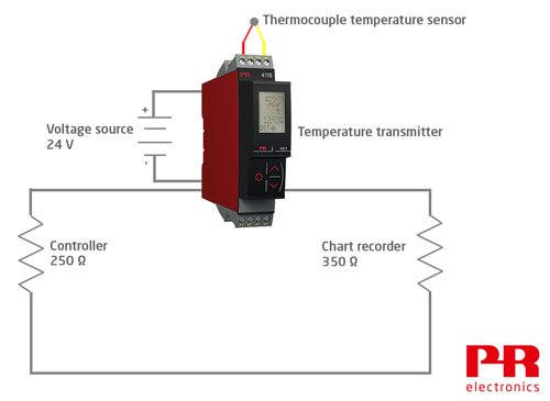
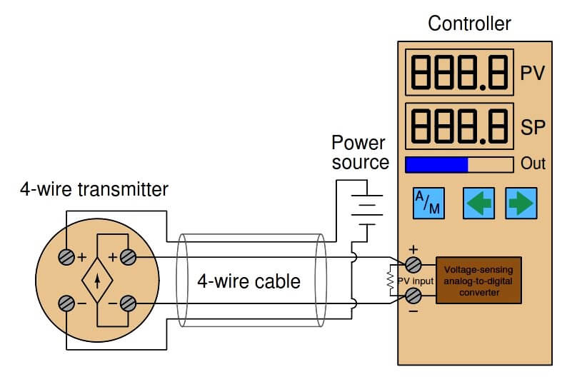
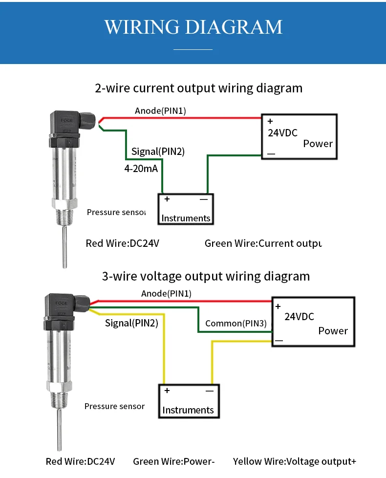
Rtd Transmitter Wiring Diagram Pdf. Temperature transmitter txblock usb rosemount 248 universal transmitters resistance detector rtd wilkerson instrument company inc 4 20 ma cur loop devices circuit what is an types uses and 3144p difference between 2 wire 3 pt100 sensor pinout features. 4-wire sensor transmitter simplified block diagram. Unlike the 2- and 3-wire transmitter representations shown in Figure 2, the 4-wire circuit has separate paths for the power current and signal current. Also, the 4-wire receiver does not share a common return (GND) with the power supply. This allows for several new isolation schemes, including ... Diagram Pt100 Transmitter Wiring Full Version Hd Quality. Rosemount 3144p temperature transmitters 5081 ph transmitter manualzz how to set up a dual sensor for the s and tutorials 2 wire rtd w 4 cr4 248 user manual 00809 0300 test 3 pyromation wiring diagram 214c sensors understand 644 programmable 20ma pt100 untitled by luppo issuu china converter 148 fisherrosemount korea full eac approved ... – The actual wiring between the transmitter and the power supply depends upon whether it is a 2-wire or a 4-wire type. – A 4-wire transmitter has 2 wires connected to a power supply, and 2 signal wires connected to the PLC. – A 2-wire transmitter has only 2 wires and is connected in series with the power supply and the PLC.
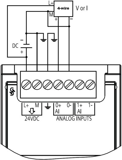
How Do You Connect A Sensor To The Analog Signal Modules Of The S7 1200 S7 1500 An Id 40913432 Industry Support Siemens
4:404to20mA #2wire #Instrumentation #TechviewAutomationandEmbeddedDiscribe about Transmitter Wiring ...10 May 2020 · Uploaded by Adarsh Mp

Principles And Differences Of 2 Wire 3 Wire And 4 Wire Transmitters Knowledge Okmarts Industrial Online Supply
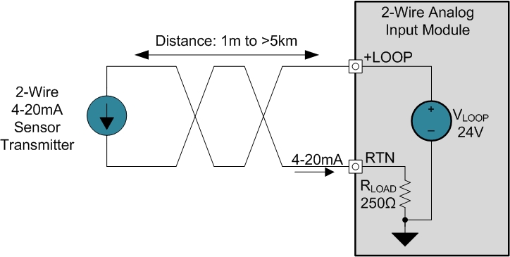
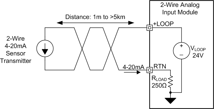
Figure 1. It is a typical usage of two-wire 4-20mA pressure transmitters for most customers showed in figure 1. After the pressure transmitter is powered on, the loop current is proportional to the pressure to generate a 4-20 mA signal by collecting the pressure. The current flow through the sampling resistor (typical 100 Ω, 250 Ω) which ...
2 Wire 4 20 Ma Sensor Transmitters Background And Compliance Voltage Part 1 Precision Hub Archives Ti E2e Support Forums
A further possibility to substantially decrease the influence of the cabling is to increase the conductor cross-section. With a cross-section of 0.5 mm 2 the line resistance is only 0.036 Ω/m or 0.1 °C/m. Both options (3/4-wire connection or increasing the cross-section) lead to a higher cost in the cabling, which can be problematic, especially in cost-sensitive markets such as machine building.

Difference Between 2 Wire 4 Wire Transmitter Current Loops Instrumentation And Control Engineering
A wiring diagram is a streamlined standard pictorial depiction of an electric circuit. 2 wire pressure transducer wiring diagram 4 20ma transmitter circuit diagram awesome 3 wire pressure transducer wiring diagram. All devices in a 4 20 ma current loop need to be supplied power from somewhere in order to function.

What Are 2 Wire And 4 Wire Transmitter Output Loops Youtube
Why Use a 4 Wire RTD? ... but you should consider using a transmitter in electrically noisy environments. 4 Wire RTD Color Code. Lead wire colors are defined in the IEC 60751-2008 standard where all wire colors are shown as in the following figure. ... 4 Wire RTD Wiring Diagram. In this circuit there are three leads coming from the RTD instead ...

4 20 Ma Transmitter Wiring Types 2 Wire 3 Wire 4 Wire
4:31analog #senor #PLC #learningPlease Subscribe to Easy PLC Tutorials for more Videos and ...4 Feb 2021 · Uploaded by PLC Programming Tutorials Tips and Tricks

Process Control Musings Deltav Version 12 Fun Facts And Features Part 3
2-wire. 3-wire. UB. 1. 1. 0V. 2 Connection diagrams. All connectors with .The model S pressure transmitter for general industrial applications is the ideal solution for customers with demanding measuring requirements. It features a very good accuracy, a robust design and an exceptional number of variants, meaning it can be suited to the widest ...
How To Connect Pressure Sensor Pressure Transducer Or Pressure Transmitter To Industrial Instrumentation Or Plc Tm Automation Instruments Co Ltd
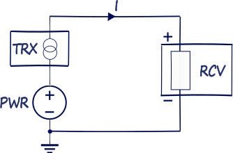
The following figures show basic transmitter connection: Figure 2. 4 Wire transmitter. 3-Wire devices. The standard also describes a Type 3 connection type, or 3-wire transmitter loop, where the Transmitter and Receiver share a ground connection with power, and the transmitter uses a third wire to connect to power outside of the current loop.

4 Wire Transmitters Current Loops Instrumentationtools
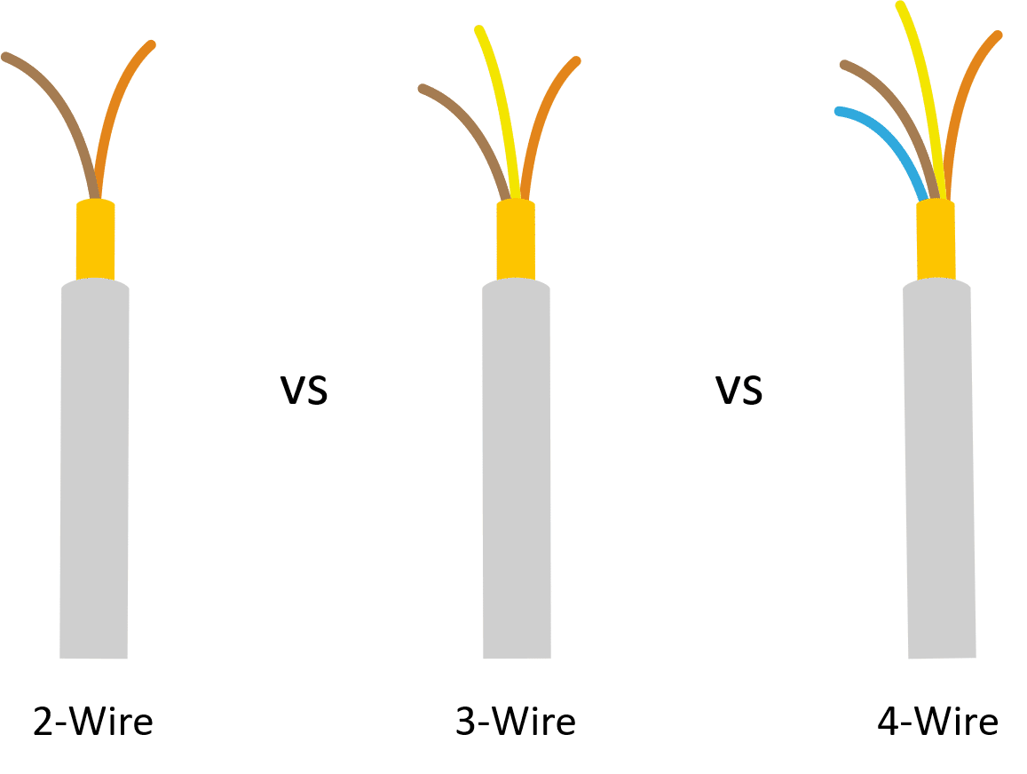
These connection methods are of great concern to the instrument engineer/technician. The 2 - Wire, 3 - Wire and 4 - Wire types are often used to describe the method of connection of electronic transmitters. However in today's rapidly evolving technological world, the 2 - Wire type transmitter is by far the most common.
Nikolay Bozov Industrial Automation And Control
Wiring Diagram 4 Wire Og Signal plete Wiring Schemas The best complementary is always to use a verified and accurate Loop Powered Transmitter Wiring Diagram that’s provided from a trusted source. A good, traditional company that has a long track cassette of providing the most up-to-date wiring diagrams easy to use is not difficult to find.
4 20 Ma Transmitter Wiring Types 2 Wire 3 Wire 4 Wire
Transmitter converts the low-level sensor signal to a HART 4-20 mA dc signal that is relatively insensitive to lead length and electrical noise. This current signal is transmitted

4 20ma Transmitter Wiring Types 2 Wire 3 Wire 4 Wire Learning Instrumentation And Control Engineering
This video demonstrates the wiring scheme of Transmitters. We have covered 4-wire transmitter, 3-wire transmitter and 2-wire transmitter.Hope this video is p...
7 Loop Powered Signal Isolator Wiring Diagrams Ato Com
2-Wire &; 4-Wire Transmitter Wiring Dia gra ms Transmitter 4 - Wire Transmitter 4 - Wire 25 mA Common 25 mA 25 mA Common 25 mA 25 mA Common 25 mA 25 mA Common 7 7 6 5 4 3 2 Output 4-20mA 1 Output 4-20mA 120Vac power ... 4-Wire Transmitter P.O. Box 847 R-Safe Specialty Newman, CA 95360 Tel: 209-862-0230 Toll-free: 1-800-860-3088 Fax: 209-862-0380 ...

Electrical Connections Wiring Guide Dylix Corporation
Here, the transmitter is not really a current source in the sense that a 4-wire transmitter is. Instead, a 2-wire transmitter's circuitry is designed to act as a current regulator, limiting current in the series loop to a value representing the process measurement, while relying on a remote source of power to motivate current to flow.

4 To 20 Ma Current Loops Made Easy
4 Wire Pressure Transducer Wiring Diagram - wiring diagram is a simplified adequate pictorial representation of an electrical circuit. It shows the components of the circuit as simplified shapes, and the skill and signal connections along with the devices. A wiring diagram usually gives guidance nearly the relative slant and bargain of ...

What Are 2 Wire And 4 Wire Transmitter Output Loops Realpars
Assortment of 4 wire transmitter wiring diagram. A wiring diagram is a streamlined standard photographic representation of an electrical circuit. It shows the components of the circuit as streamlined shapes, and also the power as well as signal links between the tools.
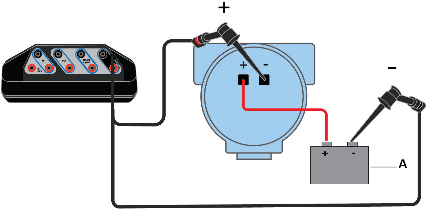
Wiring Diagrams For Hart Devices And The Field Communicator Application
3 Wire Pressure Transmitter Wiring Diagram. Pressure transducers installation and use 3 wire 4 20ma transmitter wiring technology in sensors electrical connections guide ma types 2 china low range sensor rsinstruments to 20 cur loop output signal 0 5v piezoresistive silicon.

Rs 485 Connections Faq Advantech B B Smartworx
The system is called balanced, because the signal on one wire is ideally the exact opposite of the signal on the second wire. In other words, if one wire is transmitting a high, the other wire will be transmitting a low, and vice versa. See Figure 2. Figure 2. The signals on the 2 wires of a balanced system are ideally opposite.

Basics Of Ashcroft Pressure Transmitter Performance Index Wiring Thread Type Unavoidable Inaccuracies And Mounting Knowledge Okmarts Industrial Online Supply
Example 4-20mA thermistor transmitter wiring diagram. So when the ROI-XMA Thermistor transmitter is used with the ROI-USB current measurement A-D, the PC can be used to measure a Thermistor with higher precision than a direct measurement system. The 4-20mA transmitter gain can be adjusted. This can minimize the span of the temperature sensor range.

Example 4 20ma Thermistor Transmitter Wiring Diagram Sensor Measurement Solutions

Planet Analog 4 Wire Current Loop Sensor Transmitters

Analog 3wire Transmitter Wiring Prospective Automation

2 Wire Vs 3 Wire Transmitters Ppt Download

Cressto Intelligent Pressure Transmitter Transducer With Stainless Membrane Series Sr
How To Distinguish Between Active And Passive Signals Take Cz3047 Analog Input Signal Conditioner As An

Back To Basics The Fundamentals Of Loop Powered Devices Precision Digital
What Is The Difference Between 2 Wire 3 Wire And 4 Wire Transmitters Engineers Hub
What Is 2 Wire And 4 Wire Conection Instrumentation Instrumentation Forum
2

4 Wire Rtd Evolution Sensors And Controls
4 20 Ma Transmitter Wiring Types 2 Wire 3 Wire 4 Wire
4 20 Ma Current Loops The Fundamentals

4 Wire Transmitters Current Loops Instrumentationtools
1

4 Wire Mass Flow Meter Wiring Connection Detail In Hindi Instrument Guru Youtube
2 Wire 4 20 Ma Sensor Transmitters Background And Compliance Voltage Part 1 Precision Hub Archives Ti E2e Support Forums

Current Loop Connection Divize Industrial Automation

4 20 Ma Transmitter Wiring Types 2 Wire 3 Wire 4 Wire Youtube

What Are 2 Wire And 4 Wire Transmitter Output Loops Realpars

Diagram 2 3 4 Wire Transmitter Working Principle And Related Problems
2 Wire 4 20ma Output Intelligent Pt100 Rtd Temperature Sensor Transmitter Buy 4 20ma Pt100 Temperature Transmitter Pt100 Rtd Temperature Sensor Head Mounted Temperature Transmitter Product On Alibaba Com
0 Response to "42 4 wire transmitter wiring diagram"
Post a Comment