43 free body diagram torque
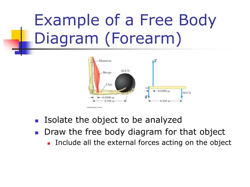
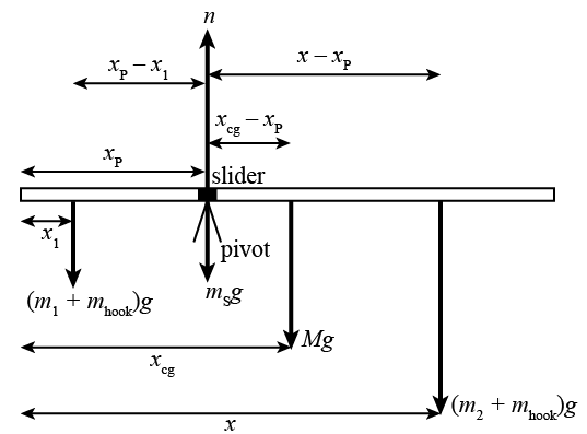
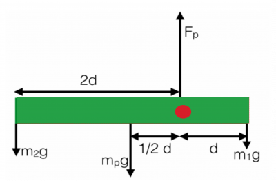
Free Body Diagrams for Torque situations usually include a weight for the object experiencing the torque, various or a single support force, and any other pushes or pulls that are acting to keep the object in equilibrium. Below is an example of a slightly more difficult free body diagram that also demonstrates two sets of "couple" forces. Basic static equilibrium examples that emphasize drawing the free body diagram, choosing an axis, and evaluating torque without bothering to work out the num...
This is something of a tricky problem, because you have to draw the free-body diagram of the entire ladder to figure out the normal forces, and then draw the free-body diagram of one half of the ladder to complete the solution. This is also what makes it a good example to look at, however. Consider first the free-body diagram of the entire ladder.
Free body diagram torque
(c) Use the free-body diagram to write a correct equilibrium condition (Figure) for torques along the axis of rotation. Use (Figure) to evaluate torque ... Free-body diagram of rotor used in rigid-body approximation With these assumptions, T,, the aerodynamic torque, was determined as a function of rotor position for any given wind speed or corresponding tip-speed ratio TSR (TSR = blade rotational velocity at equatorlundisturbed wind speed). The aerodynamic The 50N.m torque is balanced by the two torques of 35 and 15 N.m at A and B respectively. Therefore, the body as a whole is in equilibrium. Step 2 We obtain the free body diagram of the part of the shaft, by passing a plane perpendicular to the shaft at any point between A and B. So we have Σ M x = 0, this implies T AB = 35N-m.
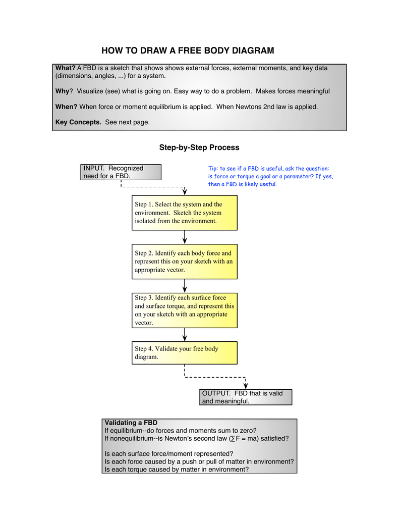
Free body diagram torque. upward force by pivot. • rod is still subject to the same forces. • no change to free body diagram. • it will rotate, but free body diagram misses this!152 pages Axial Force Diagrams and Torque Diagrams. As an alternative to splitting a body in half and performing an equilibrium analysis to find the internal forces ... Torque Free Body Diagram. torque relationship between force f torque τ linear momentum p and angular momentum l in a system which has rotation constrained in one plane only forces and free body diagrams basics mrwaynesclass identify the force acting on a body identify the direction of each acting force and draw vectors representing the forces create a pair of equations from On the free-body diagram, indicate the location of the pivot and the lever arms of acting forces—you will need this for correct computations of torques.
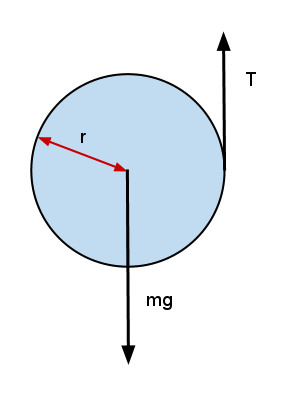
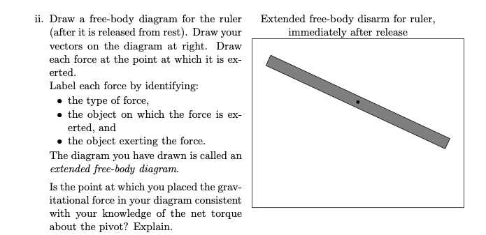
Download scientific diagram | Free body diagram for the calculation of the joint force and torque of the upper trunk seg- ment. from publication: Kinetic ... 15 Nov 2021 — Torque Diagrams. To investigate situations in static equilibrium more thoroughly, you can make use of an extended free-body diagram that shows ... A) Draw a free-body diagram. Show the torque reactions at supports A and C in the correct direction for resisting the applied torque, T. From your free-body diagram, write the equilibrium equation for the torques. Express the torsional equation of equilibrium for the shaft in terms of TA, and TC. B) what does a free body diagram involving torque look like? This is a free body diagram of a yo-yo resting on a table. The force of gravity acting on the yo-yo (green arrow) is pulling downward on the yo-yo as it would on any object in ideal circumstances.
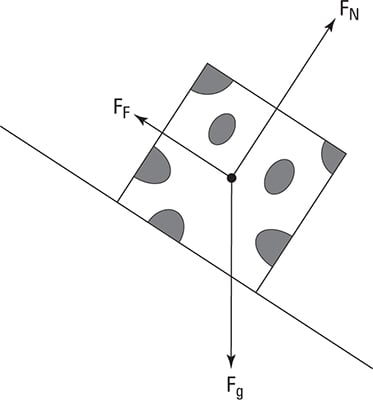
Drawing Free-Body Diagrams. Free-body diagrams are diagrams used to show the relative magnitude and direction of all forces acting upon an object in a given situation. A free-body diagram is a special example of the vector diagrams that were discussed in an earlier unit. These diagrams will be used throughout our study of physics. Torque and Angular Momentum of a Particle The figure below shows a fixed coordinate system OXY Z containing a mass m moving with velocity v, having momentum p , and being acted upon by a resultant force, f . X Y Z O ... The free body diagram depicting the torques on the body is shown below. Note the directions of the unit The 50N.m torque is balanced by the two torques of 35 and 15 N.m at A and B respectively. Therefore, the body as a whole is in equilibrium. Step 2 We obtain the free body diagram of the part of the shaft, by passing a plane perpendicular to the shaft at any point between A and B. So we have Σ M x = 0, this implies T AB = 35N-m. Free-body diagram of rotor used in rigid-body approximation With these assumptions, T,, the aerodynamic torque, was determined as a function of rotor position for any given wind speed or corresponding tip-speed ratio TSR (TSR = blade rotational velocity at equatorlundisturbed wind speed). The aerodynamic
(c) Use the free-body diagram to write a correct equilibrium condition (Figure) for torques along the axis of rotation. Use (Figure) to evaluate torque ...













0 Response to "43 free body diagram torque"
Post a Comment