43 lead tin phase diagram
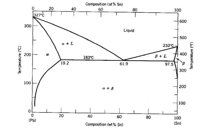
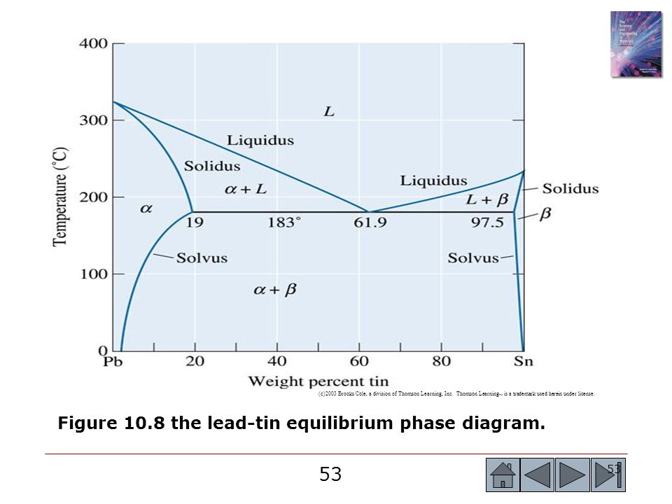
Mass out 50 grams total of your assigned lead and tin alloy. ... Tin–Lead Solder – Observations. 1. Cup #1: ... binary phase diagram for Pb/Sn solder. The maximum solubility of tin into lead has the composition of Pb-19.2 wt % Sn. Q. 3a… View the full answer Transcribed image text : Problem 3 Figure 3a and Figure 36 show the phase diagrams for two different alloy systems: load-tin, and magnesium-load. et inde H. 975 19 100 . 40 Weight Figure 3a.
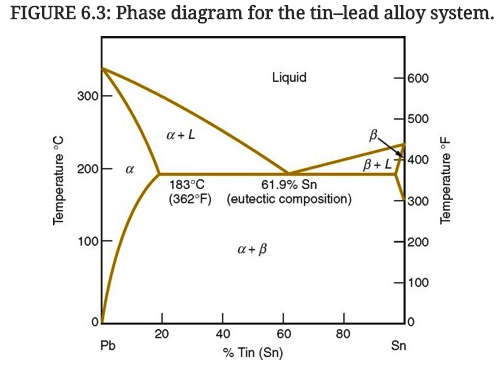
The lead-tin (Pb-Sn) phase diagram with three different solder compositions marked out; one eutectic, and two non-eutectic (Plumber's solder and a high melting ...

Lead tin phase diagram
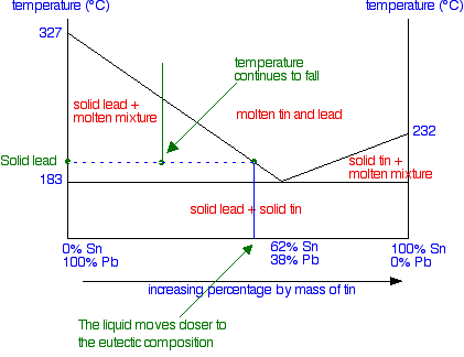
The lead-tin equilibrium phase diagram, . Figure 11-6. -- .. -- .. -. -. A. It is critical to note that binary phase diagrams typically do not incorporate ...6 pages There are two of solid phases in Tin-Lead alloy system can be seen at left and right sides of diagram. The right side solid phase is called as alpha phase and the left side solid phase is called as beta phase in Sn-Pb alloy system. Upon the upside lines of these solid phases, the alloy system turns into solid+liquid phase. Important: This is a simplified version of the real tin-lead phase diagram.In particular, it ignores the formation of solid solutions of tin and lead. You will find the correct diagram on this NIST web page.Beware that on that page, the tin-lead axis is reversed from the one I have drawn above - in other words 100% lead is on the right rather than the left.
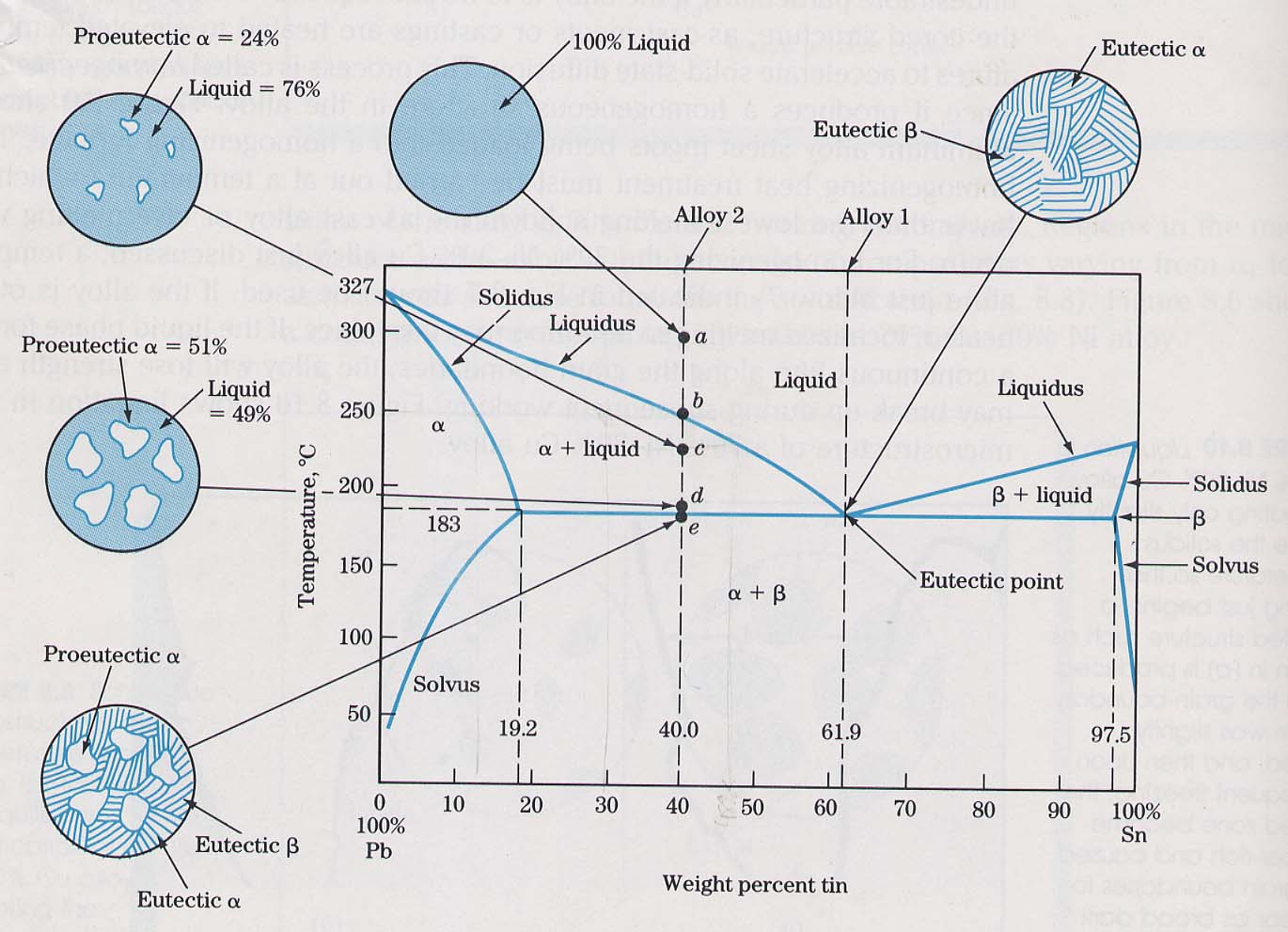
Lead tin phase diagram. One of the most important eutectic's is tin-lead (Sn-Pb) used for soldering. Another interesting example is indium-gallium (InGa) which is liquid just above ... Example using the Pb-Sn Phase Diagram. Consider a 40 wt% Sn-60 wt% Pb alloy on the lead-tin phase diagram. Part 1: At 183.1 degrees C, just above the eutectic line, a) what phase(s) is (are) present? b) what is (are) the compositions of the phase(s)? c) what is the relative amount of each phase present, in mass fraction? 21 Aug 2020 — If you had less tin in the mixture, the overall shape of the curve stays much the same, but the point at which the lead first starts to freeze ...Changing the Proportions of... · The phase diagram · Using the Phase Diagram Example - Gibbs phase rule in eutectic diagram In the double phase regions: N = 1 (the diagram is plotted for fixed pressure, 1 atm) C = 2 P = 2 F = N + C -P F = 1 By fixing the Temp one determines the compositions in the liquid and in the solid i.e. for certain Temp there is a fixed compositions In the single phase regions: N = 1 (the diagram ...
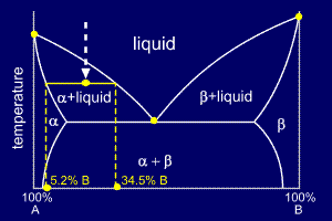
#modimechanicalengineeringtutorials, #mechanicalmagicmechanicallearningtutorials,Welcome to My YouTube Channel MODI MECHANICAL ENGINEERING TUTORIALS.This ch... Link to this course:https://click.linksynergy.com/deeplink?id=Gw/ETjJoU9M&mid=40328&murl=https%3A%2F%2Fwww.coursera.org%2Flearn%2Fmaterials-scienceThe Lead-T... MSE 2090: Introduction to Materials Science Chapter 9, Phase Diagrams 24 Binary Eutectic Systems (III) Lead – Tin phase diagram Invariant or eutectic point Eutectic isotherm Temperature, ° C Composition, wt% Sn Eutectic or invariant point- Liquid and two solid phases co-exist in equilibrium at the eutectic composition CE and the eutectic ... In this phase diagram, the two species being considered are the elements lead and tin, and the horizontal axis refers to the amount of tin in the system. This means that at the very left of this diagram, there is a system with 0% tin (pure lead) and at the right is 100%, or pure, tin.
prism is a two-component temperature-composition phase diagram with Pb Triple Eutectic 3-Dimensional Depiction of Temperature-Composition Phase Diagram of Bismuth, Tin, and Lead at 1atm. The diagram has been simplified by omission of the regions of solid solubility. Each face of the triangular a eutectic. by I Karakaya · 1988 · Cited by 78 — Thompson, 1988. 144. Bulletin of Alloy Phase Diagrams Vol. 9 No. 2 1988. Page 2 ...9 pages Important: This is a simplified version of the real tin-lead phase diagram.In particular, it ignores the formation of solid solutions of tin and lead. You will find the correct diagram on this NIST web page.Beware that on that page, the tin-lead axis is reversed from the one I have drawn above - in other words 100% lead is on the right rather than the left. There are two of solid phases in Tin-Lead alloy system can be seen at left and right sides of diagram. The right side solid phase is called as alpha phase and the left side solid phase is called as beta phase in Sn-Pb alloy system. Upon the upside lines of these solid phases, the alloy system turns into solid+liquid phase.
The lead-tin equilibrium phase diagram, . Figure 11-6. -- .. -- .. -. -. A. It is critical to note that binary phase diagrams typically do not incorporate ...6 pages

Figure 2 From Lead Free Soldering Processes In The Electronic Industry Industrial Implementation At Smes Semantic Scholar
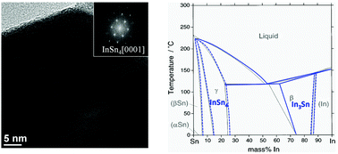
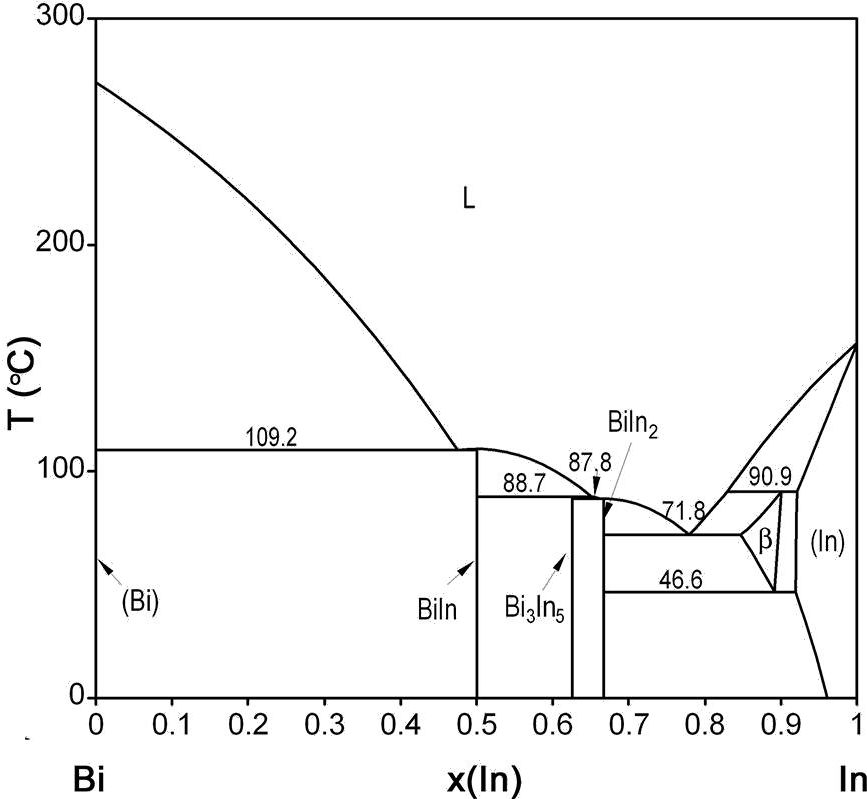
Phase Diagram And Structural Evolution Of Tin Indium Sn In Nanosolder Particles From A Non Equilibrium State To An Equilibrium State Nanoscale Rsc Publishing

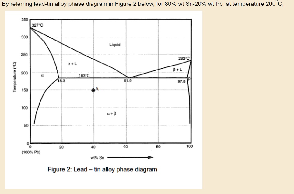
The Phase Diagram Below Shows The Cooling Process For A Lead Tin Mixture That Has 80 Wt Tin For Each Point Along The Cooling Line Determine The Appropriate Microstructure And Place It On

A Lead Tin Alloy Of Composition 30 Wt Sn 70 Wt Pb Is Slowly Heated From A Temperature Of 150 C 300 F A At What Temperature Does The First Liquid Phase Form B What Is The Composition
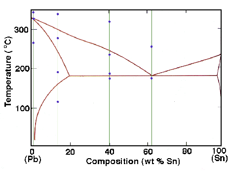
Clickable Map Of The Lead Tin Phase Diagram This Is A Netscape Extension To Html 3 0 Clickable Mapping Tutorial Http Www Eng Vt Edu Eng Materials Classes Mse2094 Notebook Cgimap Click5 Html

A Lead Tin Alloy Of Composition 90 Wt Sn 10 Wt Pb Is Slowly Heated From A Temperature Of 110 Degrees C A At What Temperature Does The First Liquid Phase Form B What











0 Response to "43 lead tin phase diagram"
Post a Comment