45 classic instruments wiring diagram
a. Black wire from a Classic Instruments signal generator b. Ground of a SN74 speedometer calibration box 7) Connect the speed signal power to the “B+” or “1” terminal on the back of the speedometer: a. Red wire from a Classic Instruments signal generator b. Power of a SN74 speedometer calibration box Download SN10K LS Engine Tach Signal Pull-Up Resistor Wiring Diagram 4/8/15 . SN11 Low Volt Light . Download SN11 Low Volt Light Wiring Diagram 7/12/12 . SN20 Tachometer Filter. Download SN20 Wiring Diagram . SN33 Deluxe Fuel Sender. Download SN33 Installation Guide . SN34 Fuel Link Module. Download SN34 Installation Guide . SN46 Gear Selector ...
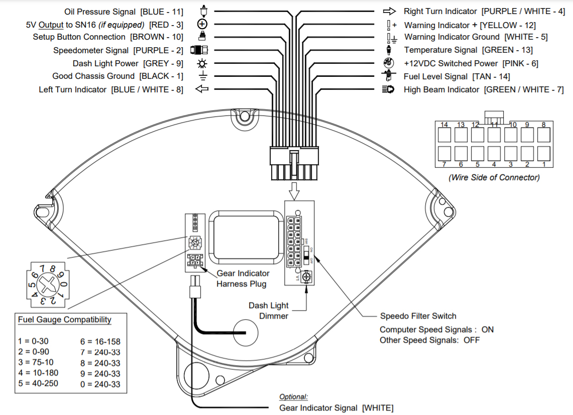
a. Black wire from a Classic Instruments signal generator (SN16 or SN16F) b. Ground of a SN74 speedometer calibration box 8) Connect the speed signal power to the “B+” or “1” terminal on the back of the speedometer: a. Red wire from a Classic Instruments signal generator (SN16 or SN16F) b. Power of a SN74 speedometer calibration box
Classic instruments wiring diagram
Wiring Diagram. Classic Instruments gets lots of calls to their tech lines and most of the time bad wiring is the root cause of gauge problems. People tend to have. Download Gauge Cluster Installation Manual Rev 6/11/15 . Welcome from the Team at Classic Instruments! Our congratulations and appreciation for your purchase of one of the finest quality sets of specialty instruments ever produced! Your instrument set has been conceived, designed, and manufactured by Classic Instruments, Inc. in the U.S.A. 4” Speedometer Wiring Diagram. Filter Switch. ON: PCM or SN16 Speed. Signals. OFF: VSS or SN96 Speed. Signals. Turn & High Beam indicator leads are.
Classic instruments wiring diagram. 14) Optional: Connect the warning indicator ground to the White wire of the gauge wire harness. Page 9. Revised: March 20, 2017. Page 9. Gauge Wiring Diagram.14 pages 9 Oct 2019 — Speedo, Tach, Volt and Oil Pressure Gauge Wiring Diagram . ... Your instrument set has been conceived, designed, and manufactured by Classic ...16 pages Welcome from the Team at Classic Instruments! Our congratulations and appreciation for your purchase of one of the finest quality sets of specialty instruments ever produced! Your instrument set has been conceived, designed, and manufactured by Classic Instruments, Inc. in the U.S.A. Revised January 22, 2016 Page 4 Remove the Original Instrument Panel 1) Disconnect the battery before beginning the replacement of the new instrument panel. 2) Remove the 5 screws holding the instrument panel to the dash. Three screws are located at the top of the instrument panel and two screws are located at the bottom of the instrument
Gauge cluster wiring diagram Bronco Tech. Yes, all EB gauge clusters were the same orientation and operation. The usual things changed such as "unleaded only" labeling, the red stripe around part of the speedometer range (vs some having no stripe) and probably a few other things. Wiring Diagrams. Gauge Dimensions. Mechanical vs. Electrical Gauges. Classic Instruments Warranty. Classic Instruments Return Policy. LS Sender Installation. Coyote Sender Locations. Testing Speedometer Signals Speedometer Signal Interface [SN74] Wiring Diagrams ... Your instrument set has been conceived, designed, and manufactured by Classic Instruments, Inc.16 pages Classic Instruments Warranty. Classic Instruments Return Policy. LS Sender Installation. Coyote Sender Locations. Testing Speedometer Signals. Wiring Diagrams. Wiring Diagrams. 01 Six Gauge Set Wiring Diagram. Six Gauge Set Wiring Diagram SNWH03 . All-American 3200/6400 Package Guide Rev 2/27/13.
Wiring Diagrams · Gauge Dimensions ... Classic Instruments receives email, fax, and phone inquiries every day. Our goal is to answer each inquiry the same ... 4” Speedometer Wiring Diagram. Filter Switch. ON: PCM or SN16 Speed. Signals. OFF: VSS or SN96 Speed. Signals. Turn & High Beam indicator leads are. Welcome from the Team at Classic Instruments! Our congratulations and appreciation for your purchase of one of the finest quality sets of specialty instruments ever produced! Your instrument set has been conceived, designed, and manufactured by Classic Instruments, Inc. in the U.S.A. Wiring Diagram. Classic Instruments gets lots of calls to their tech lines and most of the time bad wiring is the root cause of gauge problems. People tend to have. Download Gauge Cluster Installation Manual Rev 6/11/15 .
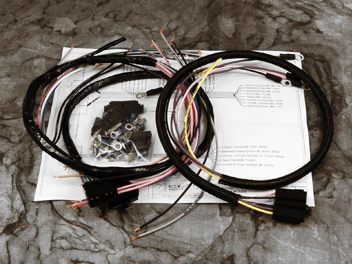
1948 79 Ford F 100 Gauge Wiring Harness Classic Instruments Universal 6 Gauge

Wiring Diagram S515 Pdf Pdf

View Topic Wiring Help Watson Kit Alternator Beetle Vw Parts

Need Help With Dash Cluster Wiring Chevy Tri Five Forum
Gauge Cluster Wiring Diagram Stangnet
A G Body Wiring Diagrams Maliburacing Com
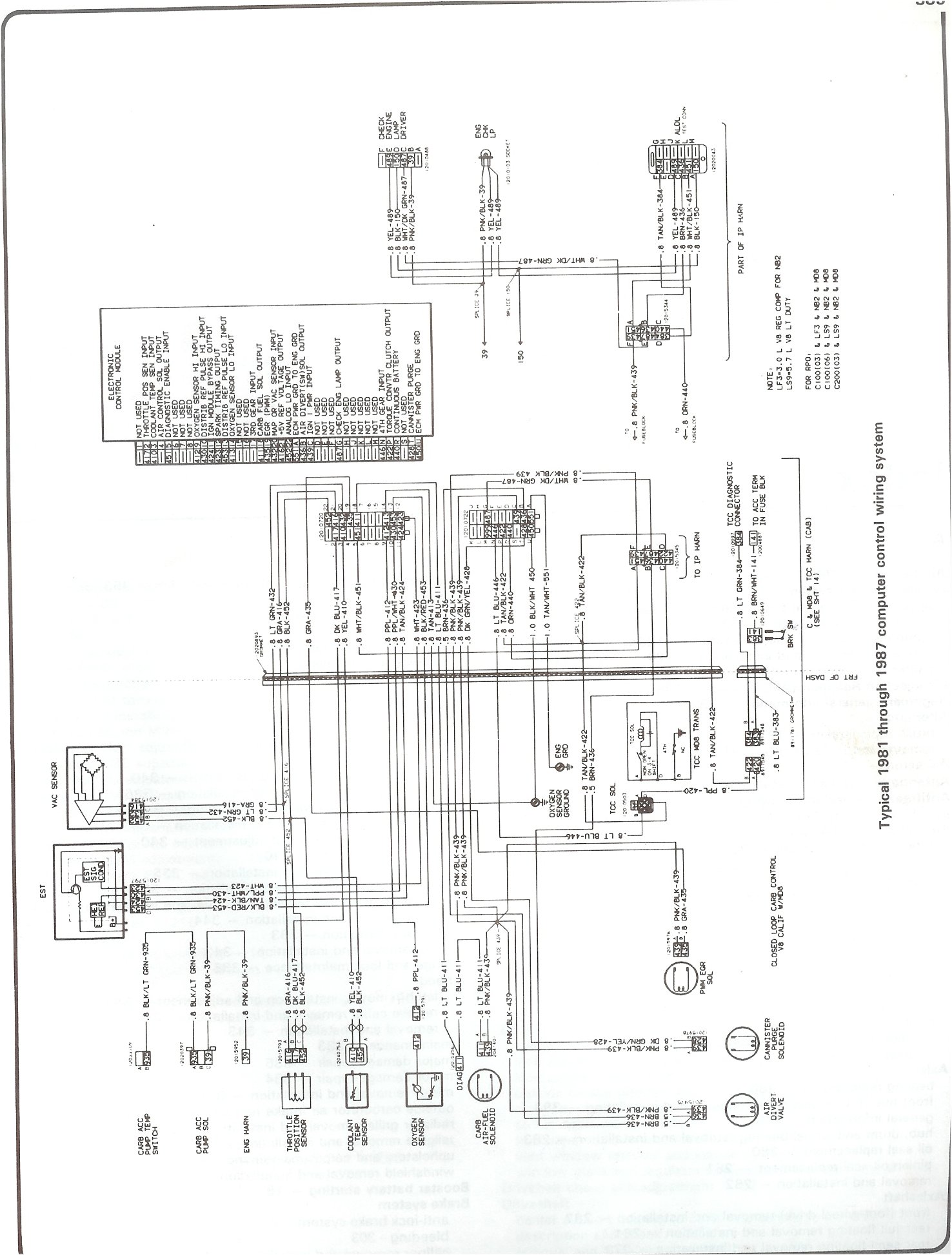
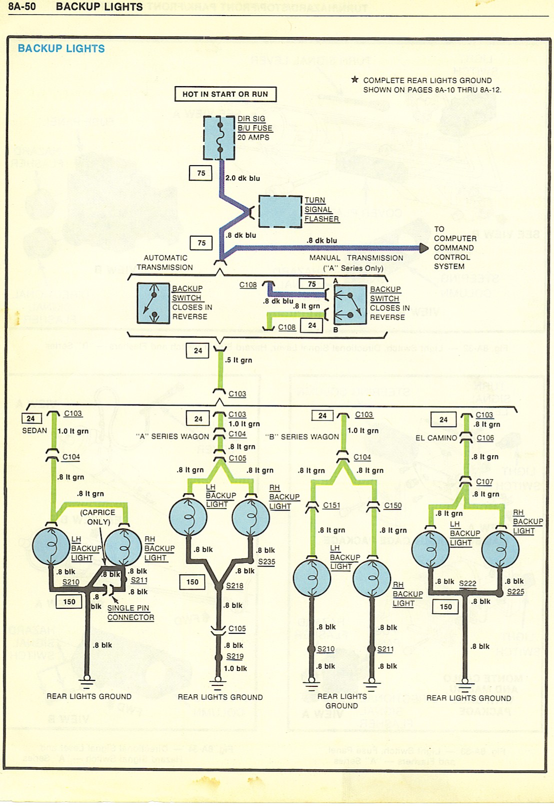
Complete 73 87 Wiring Diagrams
2

Instrument Cluster Gmc Sierra Classic 1500 2007 System Wiring Diagrams Diagramas De Cableado Para Automoviles

Yamaha Warrior 350 Wiring Diagram Images Pressauto Net Inside Electrical Diagram Yamaha Voltage Regulator

Pickup Wiring 1 Conductor Cabled Pickups Bartolini Pickups Electronics
Classic Instruments Bel Era Iii Dash Installation In A 1956 Chevy
Wiring Diagram Of The Instrument Panel With A Digital Speedometer
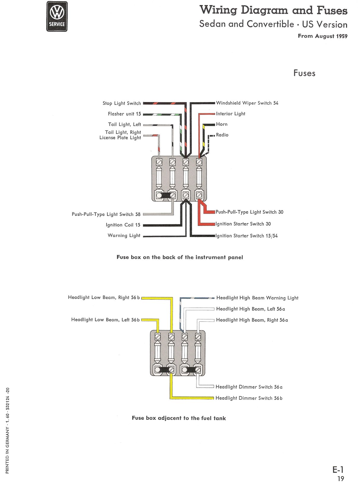
Thesamba Com Type 1 Wiring Diagrams
.jpg)
Wiring Diagrams

Installing A Dakota Digital Instrument Cluster 1967 Chevelle

1978 Malibu Classic And Monte Carlo Wiring Diagram 78 Chevy Chevrolet Schematic Ebay
Instrument Cluster Wiring Diagram The 1947 Present Chevrolet Gmc Truck Message Board Network
2
Instrument Wiring Diagram Labels Triumph Rat Motorcycle Forums

Need To Know Series No 2 Bs Au 7 Classic Vehicle Wiring Standard Wheels Alive
Instrument Panel Lights Not Working Please Help 1984 Chevy Scottsdale Chevrolet C K 10 Answered Cargurus
Pinout Gm Instrument Cluster
Wellcraft 192 Classic Instrument Panel Wiring Diagram 3d Warehouse
Digital Dash Wiring Diagram And Or Pinout Diagram
1970 Plymouth Roadrunner Wiring For B Bodies Only Classic Mopar Forum
Tech Videos

Vasu Athaly Vasuathaly Profile Pinterest

1977 900ss Wiring Diagram Schematic In Color Ducati Ms The Ultimate Ducati Forum
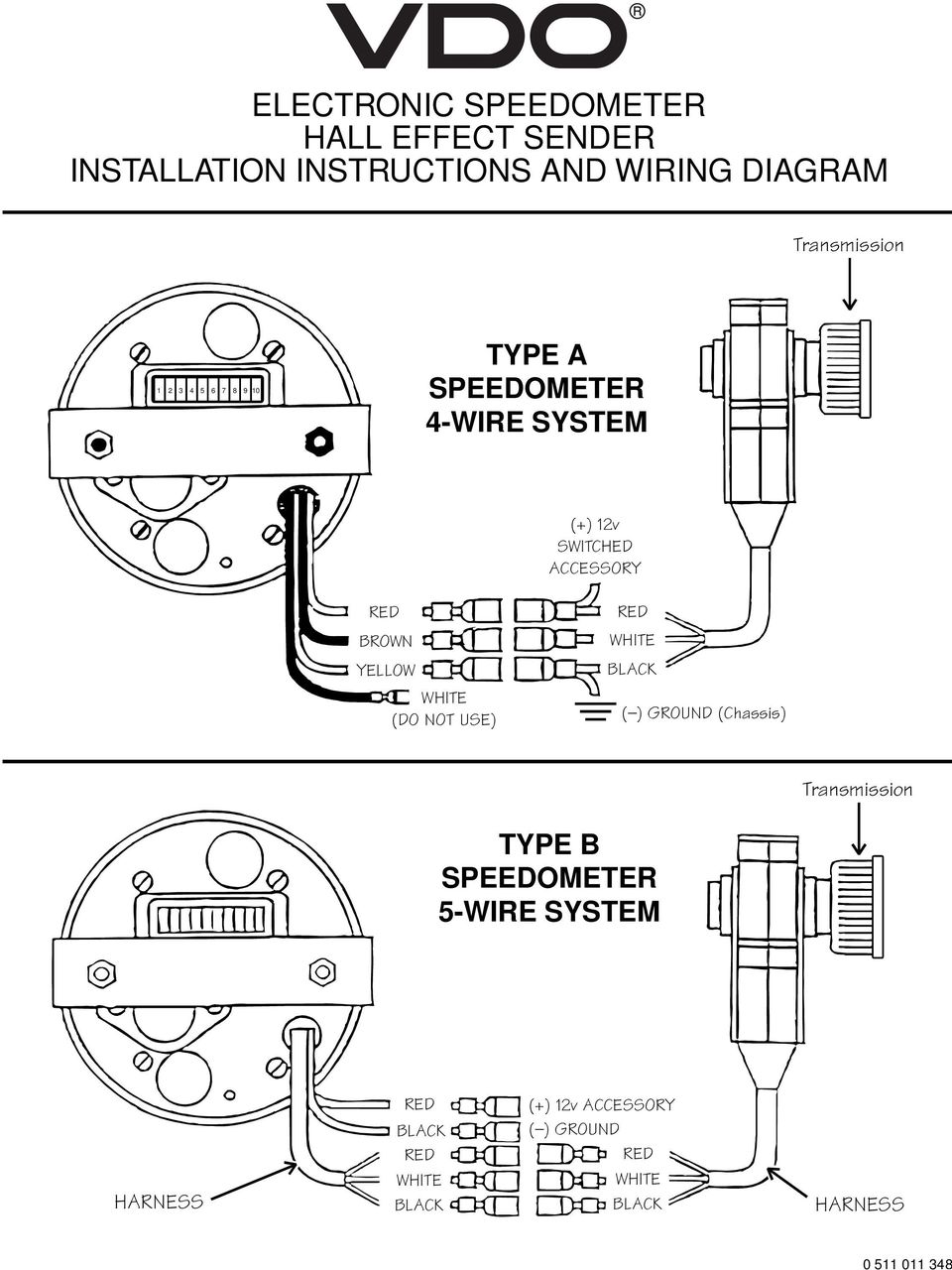
Vdo Electronic Speedometer Hall Effect Sender Installation Instructions And Wiring Diagram Type A Speedometer 4 Wire System 5 52 1 2 7 Pdf Free Download
1

Jual Produk Pickup Gitar Hss Not Termurah Dan Terlengkap November 2021 Bukalapak

Wiring Diagrams Bartolini Pickups Electronics
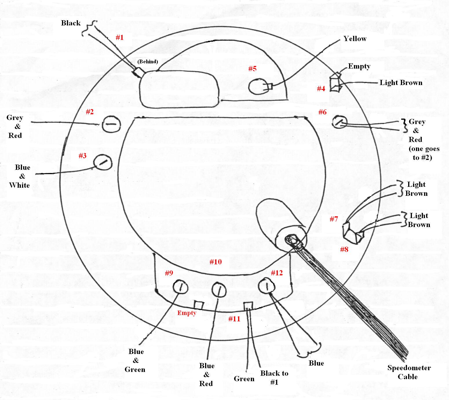
Remove Install Instrument Cluster Speedometer Cable

Wiring Diagram For Classic Instruments Tachometer Dolphin Gauges Wiring Schematic

Correcting An Inaccurate Gas Gauge With Classic Instruments Fuel Link
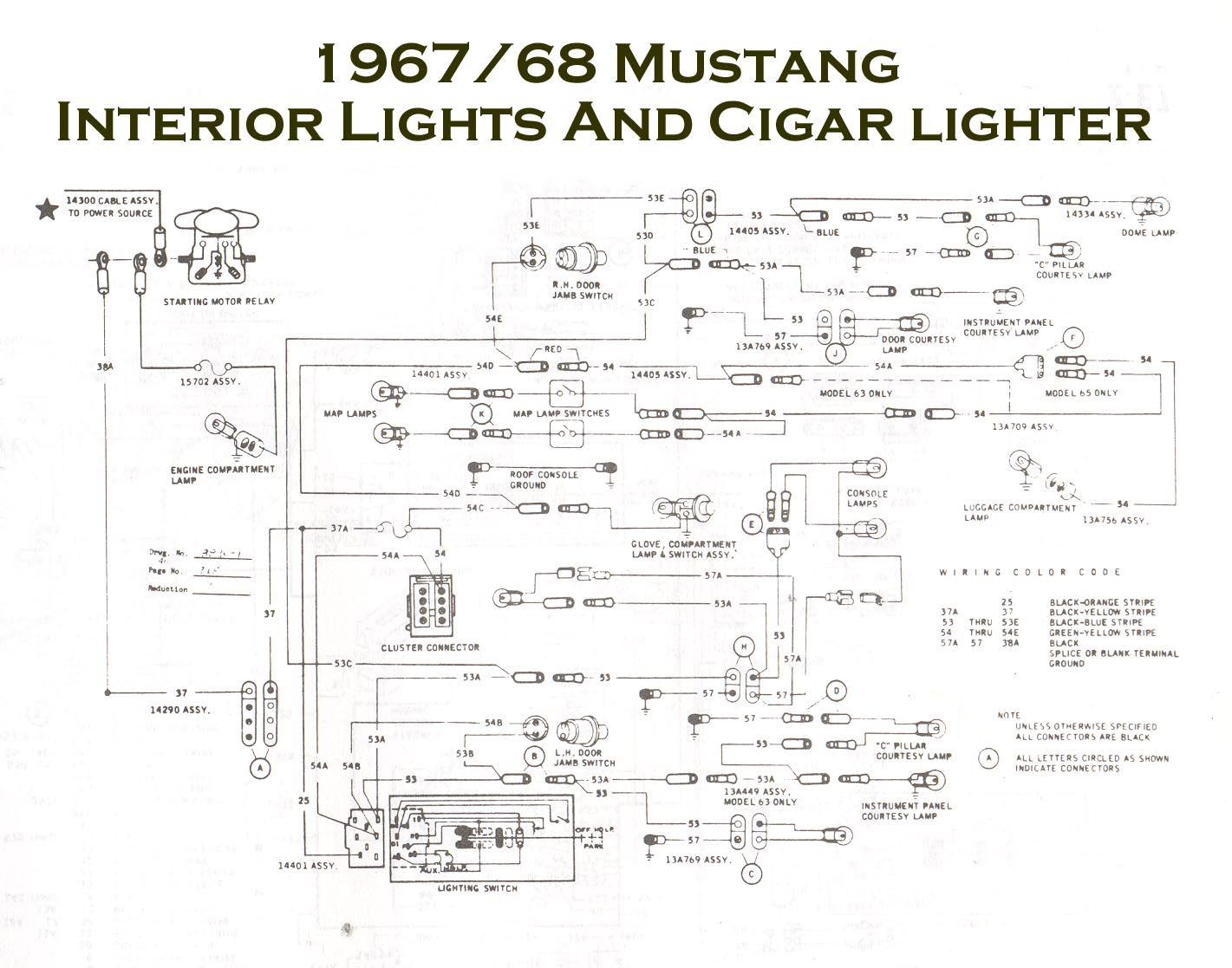
Vintage Mustang Wiring Diagrams
Classic Instruments Calibrating Speedometer

Common Electric Guitar Wiring Diagrams Amplified Parts
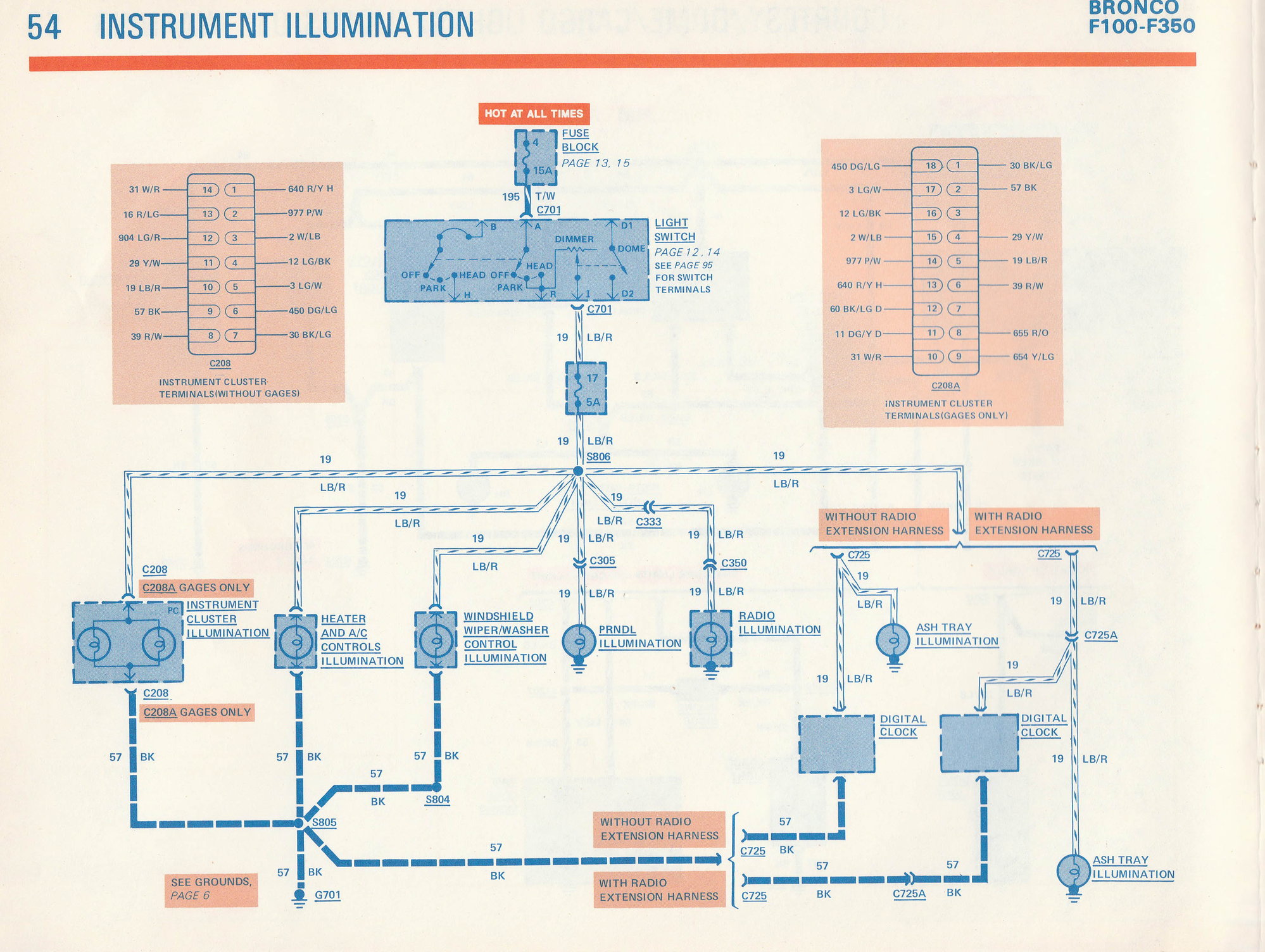
1981 F100 Gauge Cluster Wiring Diagram Ford Truck Enthusiasts Forums
5 Tips For Perfectly Working Classic Instruments Gauges

Classic Instruments Inc Instrument Manual For Classic Instruments And Sending Units Instrument Adjustment Troubleshooting Guide Pdf Free Download
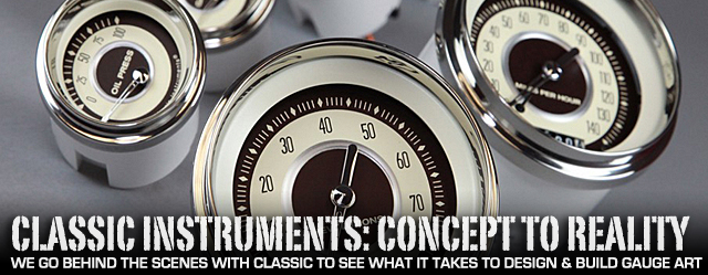
Classic Instruments The Art Of Classic Automotive Gauge Design Street Muscle

Polo Wiring Diagram Questions Answers With Pictures Fixya
Wiring Diagrams Archives Morelli Guitarsmorelli Guitars
0 Response to "45 classic instruments wiring diagram"
Post a Comment