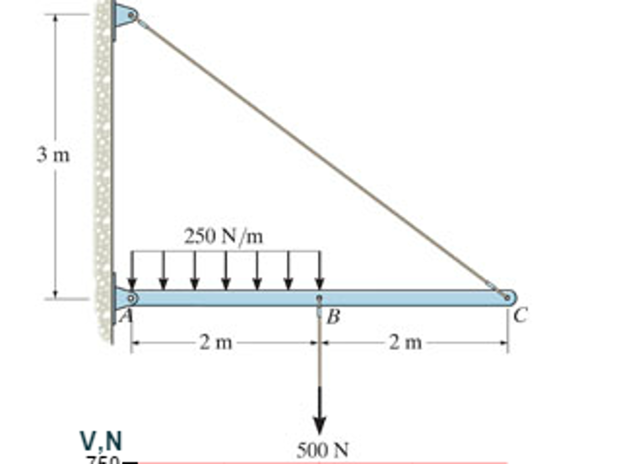
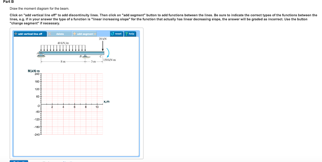
45 draw the shear diagram for the beam. 7.93
A wide flange beam, with wider flanges and web than the I-beam, can handle more weight, but this makes it heavier overall. Construction Beams. Different types of beams are used in the construction of buildings and structures. These are horizontal structural elements that withstand vertical loads, shear forces, and bending moments. R. K. Bansal · 2010 · Strains and stresses... Ra = 7.93 kN , R2 = 5.07 kN ] 6. A fixed beam AB of length 6 m is having moment of intertia I = 5 x 106 mm4 . ... Draw S.F. and B.M. diagrams also .
Academia.edu is a platform for academics to share research papers.
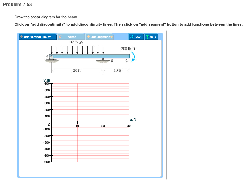
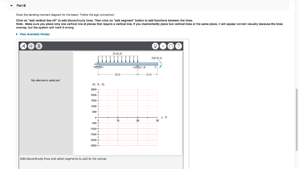
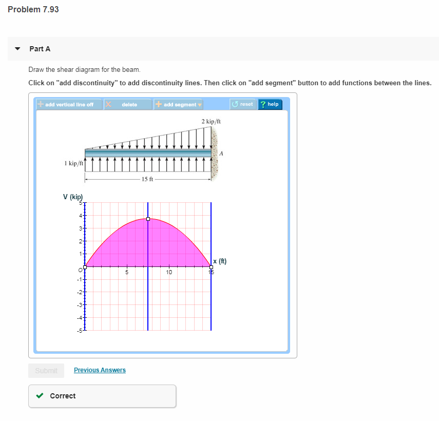
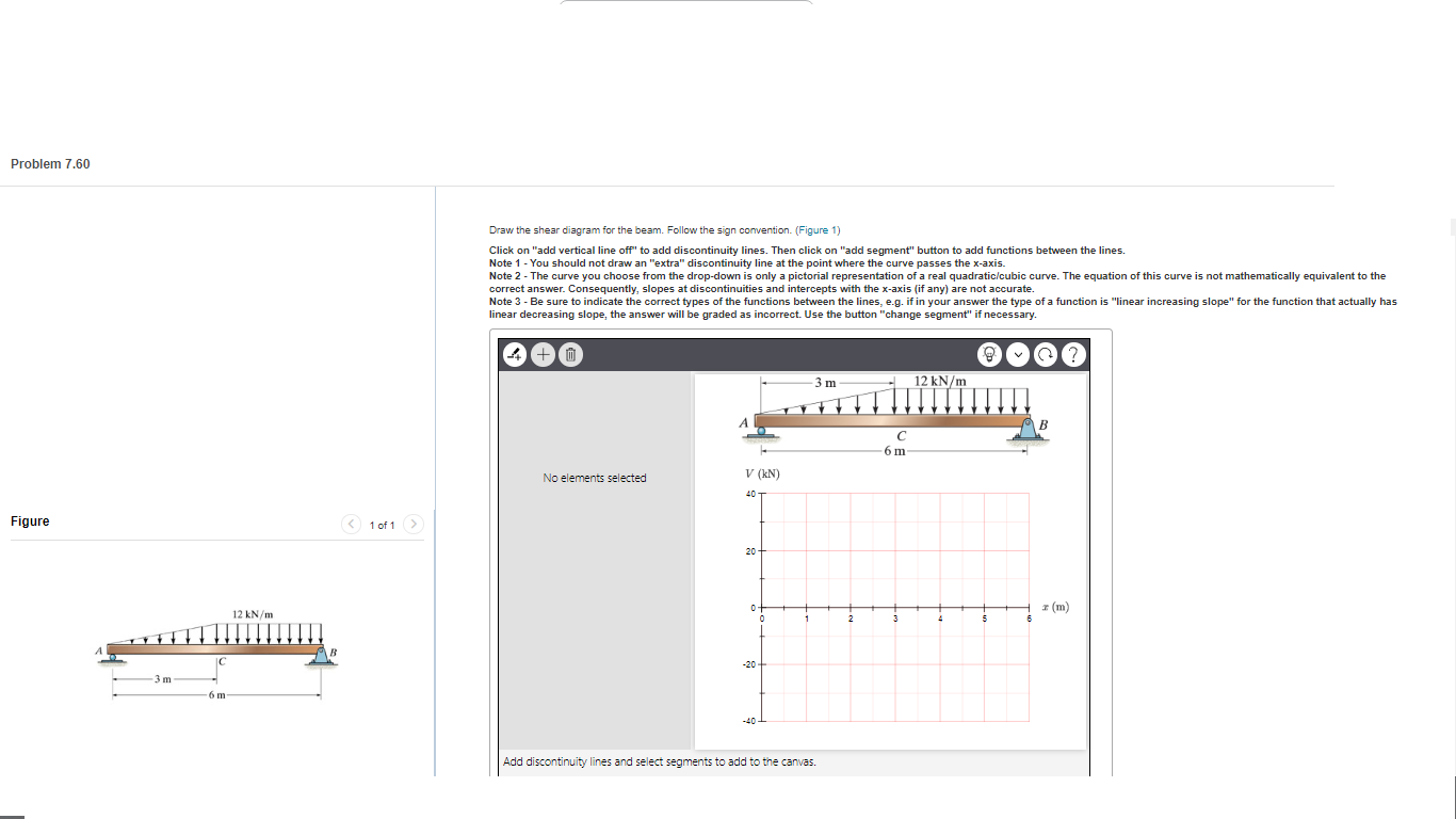
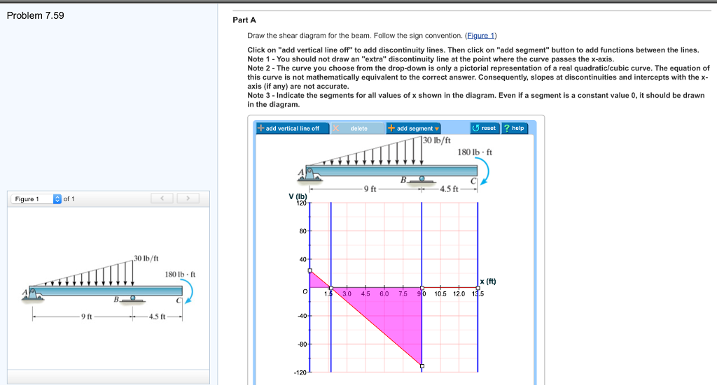
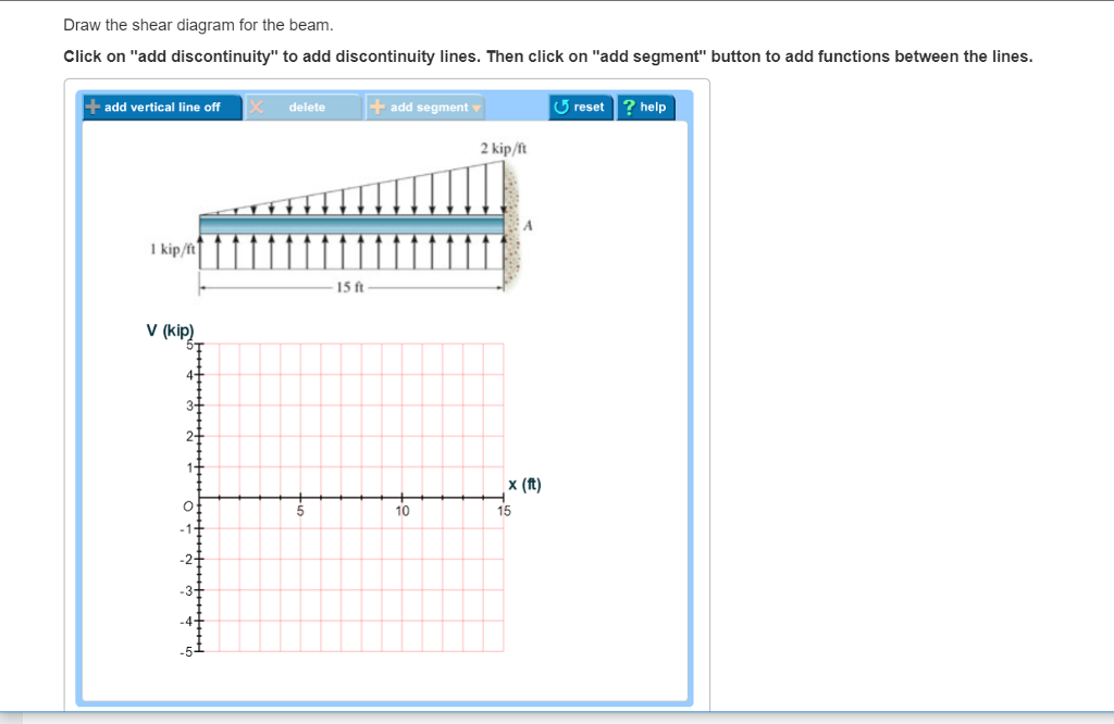
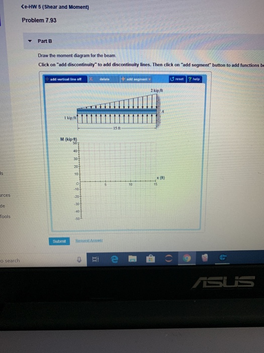
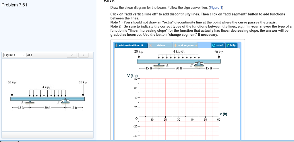
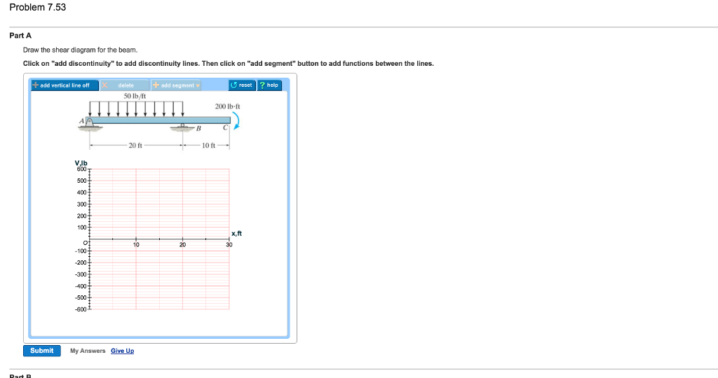
Draw the shear diagram for the beam. 7.93
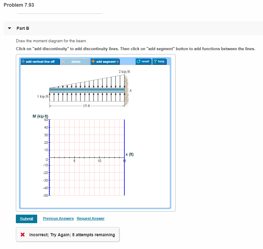
this book is a excellent good with easy to follow examples and solution that will aid any civil engineer May 28, 2018 · The free-body diagram of the beam’s segment sectioned through the arbitrary points within these two regions are shown in Figs. b and c. Region , Fig. b (1) a (2) Region , Fig. c (3) a (4) The shear diagram shown in Fig. d is plotted using Eqs. (1) and (3). The location at which the shear is equal to zero is obtained by setting in Eq. (1). Draw the shear and moment diagrams for the beam shown in Fig. 6–4a. ... The moment of inertia of the steel beam is Iz. 7.93 106 mm4, and its cross-sectional.39 pages
Draw the shear diagram for the beam. 7.93. What are the reactions on the beam at A and B? Refer to Fig. 5-14(a). 1000 N OON 1 * Зш A m Ш. 372.4 N ,llmi 0 6m (a) Fig. 5-14 SOLUTION Assume the beam bends so that the wall pushes up at A and down at В on the beam. Draw the free-body diagram showing at the midpoint the gravitational force 372.4 N C.8 m X 10 kg/m X 9.8 m/s2). See Fig. 5-14F). For the given simply supported beam: If P=84 N/m, W=84 N/m, L1=7.93 meter, L2=1.33 meter A L1 L2 Calculate the vertical reaction at A. check_circle ... Emphasis on Free-Body Diagrams. Drawing a free-body diagram is particularly important when solving problems, and for this reason this step is strongly emphasized throughout the book. In particular, special sections and examples are devoted to show how to draw free-body diagrams. Specific homework problems have also been added to develop this ... Question: 7.93 Draw the shear diagram for the beam. This problem has been solved! See the answer ...
7.93 Draw the shear diagram for the beam. Jan 11 2021 10:54 PM. 1 Approved Answer. Amol A answered on January 13, 2021. 5 Ratings, (18 Votes). Maxm SF =.1 answer · Top answer: Maxm SF = 3.75 kip at centre. R. K. Bansal · Strength of materialsDraw the S.F. and B.M. diagrams for a fixed beam , carrying an eccentric load . ... The moment of inertia of the beam is 5x10 mm and value of E for the beam ... draw free-body diagrams of bolt HJ and of the portion of the bolt located between the two planes (Fig. 1.19). Observing that the shear P in each of the sections is P = F∕2, the average shearing stress is τave = P F∕2 F = = A A 2A (1.10) H FC F K P K' L F L' P FD J (a) (b) Fig. 1.19 (a) Diagram of bolt in double shear; For the beam and loading shown, (a) draw the shear and bending-moment diagrams, (b) determine the maximum absolute values of the shear and bending moment.217 pages
Draw the shear and moment diagrams for the beam shown in Fig. 6–4a. ... The moment of inertia of the steel beam is Iz. 7.93 106 mm4, and its cross-sectional.39 pages May 28, 2018 · The free-body diagram of the beam’s segment sectioned through the arbitrary points within these two regions are shown in Figs. b and c. Region , Fig. b (1) a (2) Region , Fig. c (3) a (4) The shear diagram shown in Fig. d is plotted using Eqs. (1) and (3). The location at which the shear is equal to zero is obtained by setting in Eq. (1). this book is a excellent good with easy to follow examples and solution that will aid any civil engineer


0 Response to "45 draw the shear diagram for the beam. 7.93"
Post a Comment