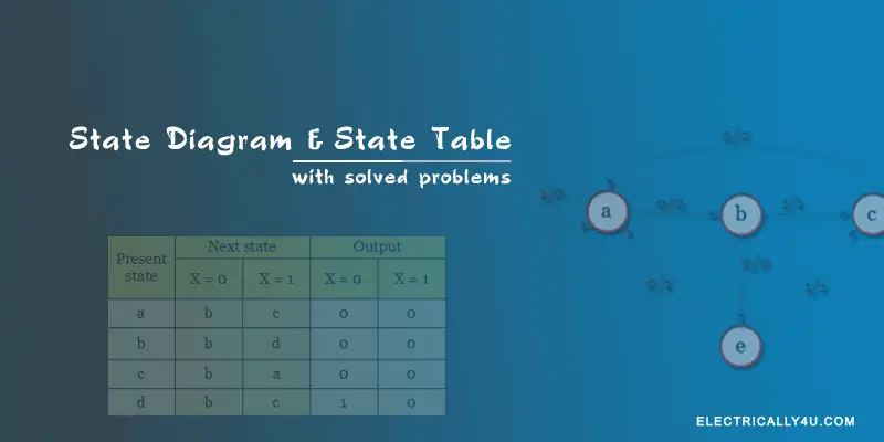
45 state table and state diagram
z Finite state machine design procedure y Verilog specification y Deriving state diagram y Deriving state transition table y Determining next state and output functions y Implementing combinational logic. State diagrams are a familiar technique to describe the behavior of a system. They describe all of the possible states that a particular object can get In most OO techniques, state diagrams are drawn for a single class to show the lifetime behavior of a single object. There are many forms of state...
A state diagram is used to represent the condition of the system or part of the system at finite instances of time. It's a behavioral diagram and it represents the behavior using finite state transitions. State diagrams are also referred to as State machines and State-chart Diagrams.
State table and state diagram
• A state diagram is used for a synchronous circuit. It shows: - the circuit state - the • We will look at the Moore model first: - a circle is drawn for each state - the value of the state and the outputs are written inside each circle - arrows • Introduction to Moore and Mealy state diagrams • State tables. Classes: 09. Synchronous sequential circuits: State table, state diagram, state assignment, state minimization; Sequential circuits. machine, state equivalence and machine minimization of completely specified or incompletely specified machines, partition method, Merger table and graph... The state table representation of a sequential circuit consists of three sections labeled present state, next state and output. In this diagram, a state is represented by a circle, and the transition between states is indicated by directed lines (or arcs) connecting the circles.
State table and state diagram. description using state names. 2. Minimize number of states (optional). 3. State Assignment: Choose state variables and assign bit. combinations to named states. 4. Build transition/output table from state/output table (or state. diagram) by substituting state variable combinations instead of state... A state machine models behavior defined by a finite number of states (unique configurations), transitions between those states, and actions (outputs) within each state. A state machine can be represented by a state diagram and/or state transition tables. It includes a state diagram, state table, reduced state table, reduced state diagram. Let us discuss them in detail. To construct the reduced state diagram, first build the state table for the given state diagram, find the equivalent states, remove the redundant state, draw the reduced state table and... State diagram essentially is a state machine, consisting of states, transitions, events, and activities. While activity diagram shows a flow of control from For example, the internal state diagram of a state machine and its corresponding state table are shown in Figure 9.4. It will be assumed that the...
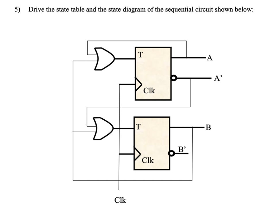
This is one of a series of videos where i cover concepts relating to digital electronics. Flip flop output combination present state. Using the state diagram, we can create a transition table which will dictate the combinatorial part of the sequential circuit. Depending on the type of memory element used (e.g. JK flip-flops, D flip-flops), the combinatorial logic that feeds into the memory must be implemented differently. This is one of a series of videos where I cover concepts relating to digital electronics. In this video I talk about state tables and state diagrams. 2. Draw state graph (to describe state machine behavior) 3. Construct state table (from state graph) 4. Perform state reduction (if necessary) 5. Encode states (aka. state assignment) 6. Create state-assigned table 7. Select type of Flip-Flop to use 8. Derive Flip-Flop input equations and FSM...
I drew a state-transition diagram — just boxes and arrows — based on the information in the table to show the various states and the allowed changes between them. In this way, I discovered two missing requirements, specific combinations of states and actions that did not have a defined outcome. Introduction to State Table, State Diagram & State Equation. Digital Logic - State Tables and State Diagrams. Understanding State Machines, Part 1: What Are They? UML Behavioral Diagrams: State Transition Diagram - Georgia Tech - Software Development Process. Each internal state is represented in the state diagram by a circle containing an arbitrary number or letter ; transitions are shown by arrows labelled with the particular input State Table: Alternatively: Example 2. A pulsed sequential circuit has two input pulses x1, x2 and a single output Z. Z changes to... A state diagram is a type of diagram used in computer science and related fields to describe the behavior of systems. State diagrams require that the system described is composed of a finite number of states; sometimes, this is indeed the case, while at other times this is a reasonable abstraction.
Circuits with Flip-Flop = Sequential Circuit Circuit = State Diagram = State Table State Minimization Sequential Circuit Design Example: Sequence Detector Example: Binary Counter.

Sometimes this is indeed the case while at other times this is a reasonable abstraction. A state diagram shows the behavior of classes in r...
State Tables (sometimes called transition Table) can be made by two methods , Now consider the circuit with D-Flip Flop , First Form of State Table State Diagram is made with the help of State Table. The Binary number inside the circle represent the Present State of Flip-Flop .
The state table representation of a sequential circuit consists of three sections labeled present state next state and output. The s...

Step 1: Making a state table. A basic state diagram. Overlapping occurrences of the pattern. Filling in the other arrows. Step 1: Make a state table based on the problem statement. The table should show the present states, inputs, next states and outputs.

• Input Equations • State Table • State Diagram • We'll use the following example. Mealy and Moore Models. • Preceding Example: Output depends on present state and input. This is called the Mealy Model.
A state diagram is also known as a state transition diagram or state chart. Learn how to make one and see state diagram examples. Specifically a state diagram describes the behavior of a single object in response to a series of events in a system. Sometimes it's also known as a Harel state chart...
Given a state table (or state diagram) and a state assignment, the task of implementing a nite-state machine is a simple one of synthesizing the next-state and output logic functions. For a one-hot state encoding, the synthesis is particularly simple as each state maps to a separate ip-op and all edges in...
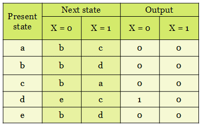
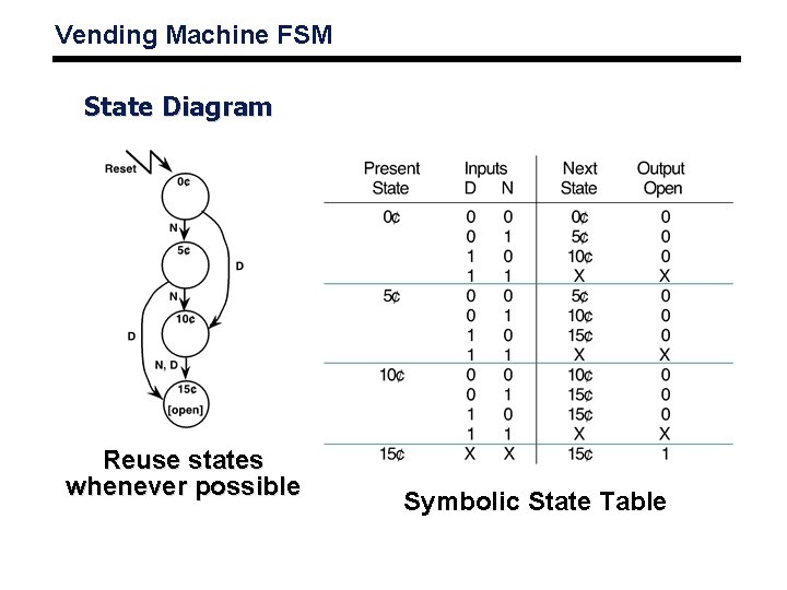
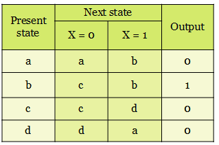
State Table The state table representation of a sequential circuit consists of three sections labelled present state, next state and output. State Diagram In addition to graphical symbols, tables or equations, flip-flops can also be represented graphically by a state diagram.

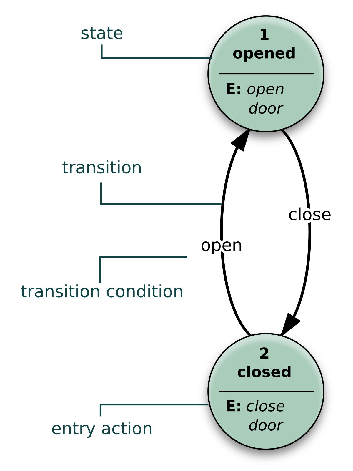
A state diagram consists of states, transitions, events, and activities. You use state diagrams to illustrate the dynamic view of a system. They are especially important in modeling the behavior of an interface, class, or collaboration.
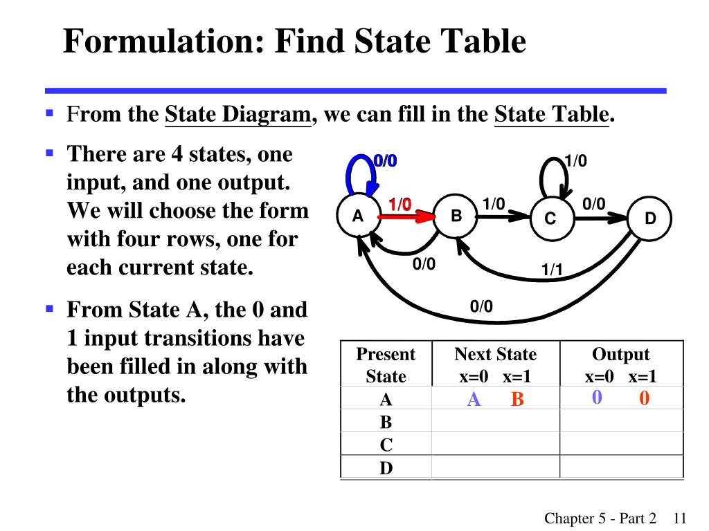
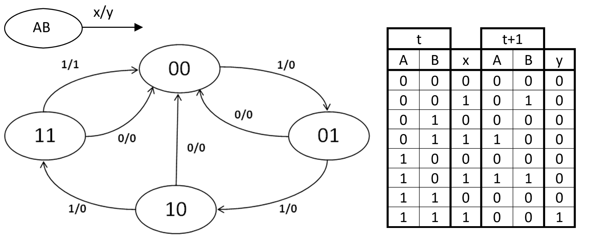
Presentation on theme: "STATE DIAGRAM AND STATE TABLES"— Presentation transcript 3 State diagram State transition diagram a circle: a state a directed lines connecting the circles: the transition between the states Each directed line is labeled "inputs/outputs" state: A B input: x.

The state table representation of a sequential circuit consists of three sections labeled present state, next state and output. In this diagram, a state is represented by a circle, and the transition between states is indicated by directed lines (or arcs) connecting the circles.

Classes: 09. Synchronous sequential circuits: State table, state diagram, state assignment, state minimization; Sequential circuits. machine, state equivalence and machine minimization of completely specified or incompletely specified machines, partition method, Merger table and graph...

• A state diagram is used for a synchronous circuit. It shows: - the circuit state - the • We will look at the Moore model first: - a circle is drawn for each state - the value of the state and the outputs are written inside each circle - arrows • Introduction to Moore and Mealy state diagrams • State tables.


0 Response to "45 state table and state diagram"
Post a Comment