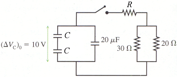
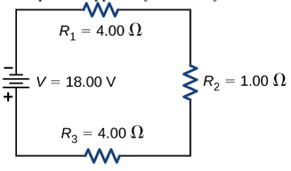
40 consider the circuit in the diagram below, in which r = 11 ω.
Given : Circuit diagram can be rearranged as shown below : It forms a wheatstone's bridge It is the condition of null point when no current flows through BD arm, i.e. 5 Ω. Resistances P = (1 Ω) and R = (2 Ω) are in series; Similarly, Resistances Q = (2 Ω) and S in series, Question 66. Understanding the circuit layout. The combination of N-P-N transistor, R 1, R 2, R L, R E and V CC function as internal or basic amplifier to provide voltage amplification or voltage gain A V = 1/β.Also, the output voltage V out will be 180° out of phase with the effective input voltage V in.; The three identical RC sections form the feedback network to provide signal path from the output ...
VR12.5 Compatible Synchronous Buck MOSFET Drivers The NCP81161 is a high performance dual MOSFET gate driver optimized to drive the gates of both high−side and low−side power MOSFETs in a synchronous buck converter.

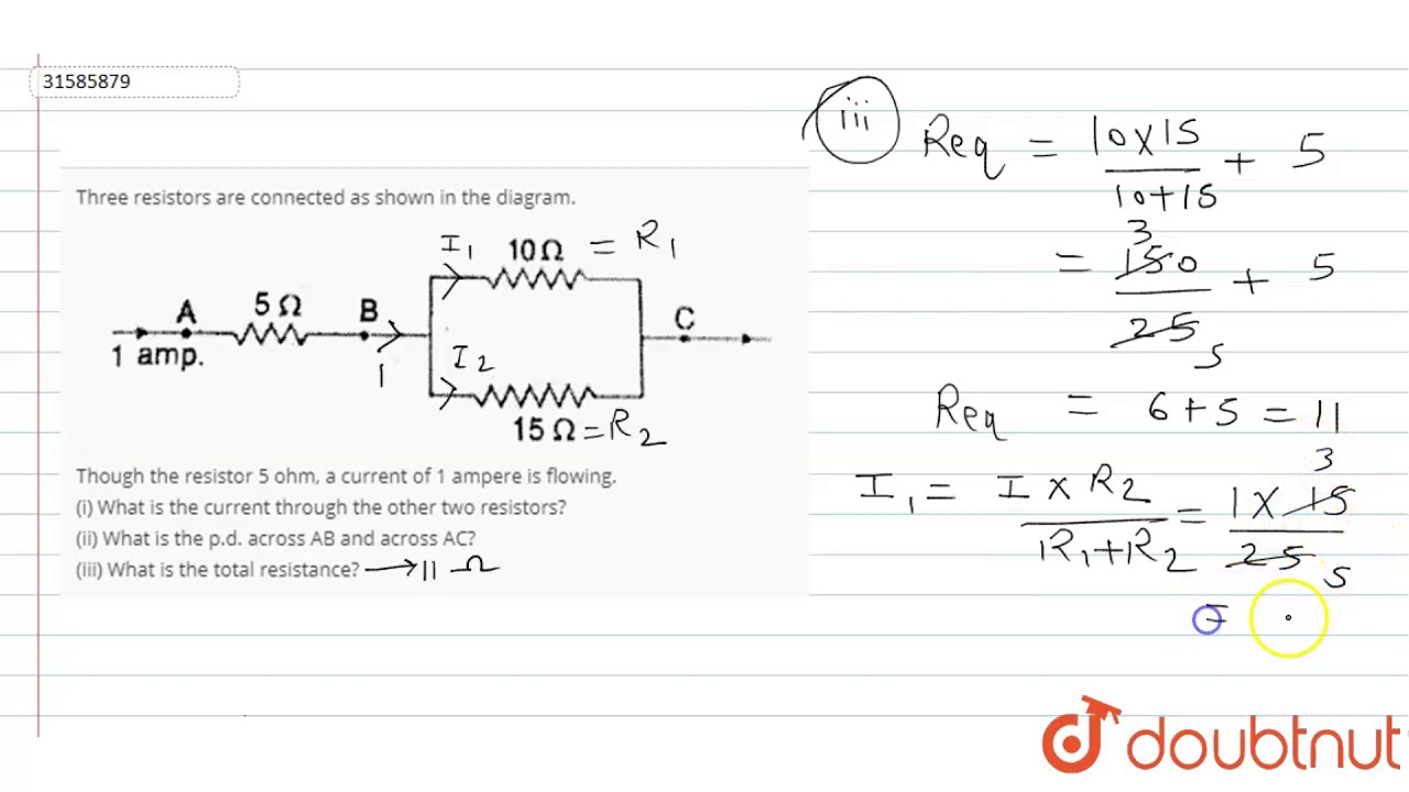
Consider the circuit in the diagram below, in which r = 11 ω.
In a space below draw a diagram showing all the elements connected in one electrical circuit that can provide the maximum rate of heat produced. Use two meters in your circuit, the y will help to measure the heat rate. The battery has an emf of 12 V and an internal resistance of 0.5 Ω and each heating 6. The diagram below shows a typical ... In the circuit diagram is given below resistors R 1, R 2 and R 3 of 5 Ω, 10 Ω and 20 Ω respectively are connected as shown in fig. Calculate: (A) Current through each resistor (B) The total current in the circuit (C) The total resistance in the circuit Solution: • The diagram below illustrates the difference between a DC and AC. 11/29/21 23 Fig 2.1: ... Potential Difference • The potential difference between two points in an electric circuit is the work done when a coulomb of charge passes between the points. ... (Ω). 11/29/21 25. 2. Basic electrical measurements contd.
Consider the circuit in the diagram below, in which r = 11 ω.. Due to the EGaIn interconnection, the circuit patch can accept a tensile strain of 88.4-95.8%, the corresponding tensile (release) cycle resistance increases (decr eases) slightly in the 40% Together with the AC current at a 1 ω frequency, the voltage of the patterns had a 3 ω angular frequency, which is related to temperature fluctuations. Figure 1c demonstrates our home-made electrical circuit for the 3 ω technique. A 7265 phase-locked amplifier was used to record the third and first harmonic voltages of the patterns. Nov 23, 2021 · This section is dedicated to tools every electrical engineer can use in daily work. These spreadsheets developed by enthusiasts will make your job much more easier, alowing you to shorten the time used for endless calculations of power cables, voltage drop, power factor, circuit breakers, capacitors, cable size, power transformers etc. RLC Circuits 1. Construct a diagram of the basic RLC Circuit and construct the differential equation. Make sure that you include what the variables in the differential equation mean. 2. Suppose that you have a circuit with a resistance of 2 Ω, inductance of 2 11 H and a capacitance of 11 60 F.
Electrical Engineering Archive: Questions from November 27, 2021. a) Find all the poles and zeros of the amplifier and draw the amplitude and phase Bode curve. (See Bias Point in Pspice to see parasitic capacities and small signal parameters.) In the Analysis simula. May 09, 2019 · Example 1: If the resistance of an electric iron is 50 Ω and a current of 3.2 A flows through the resistance. Find the voltage between two points. Solution: If we are asked to calculate the value of voltage with the value of current and resistance given to us, then cover V in the triangle. Now, we are left with I and R or more precisely I × R. In the circuit diagram given below, three resistors R 1, R 2, and R 3 of 5 Ω, 10 Ω and 30 Ω, respectively are connected as shown. Calculate : (a) current through each resistor. (b) total current in the circuit. (c) total resistance in the circuit. Solution : Question 25: A p.d. of 4 V is applied to two resistors of 6 Ω and 2 Ω connected in ... Physics Archive: Questions from November 28, 2021. 129 Problem No. 3. A homogenous ladder 12 ft long and weighing 30 lbs leans on a smooth vertical wall. It is prevented from sliding by a cable attached as shown. Find the tension in the cable if a man. 0 answers.
Because the frequency multiplier designed in this paper is in the 275 GHz frequency band, the parameters of the Schottky varactor chip of ACST are as follows: zero bias capacitance C j 0 is 43 fF, series resistance R s is 4 Ω, ideality factor n is 1.1, and reverse saturation current I s a t is 6 × 10 −16 A. Current shunt feedback amplifier shown in the Fig. 5.17 is a two-stage amplifier with the emitter resistance R E2 of the second stage amplifier unbypassed and a resistor R F is connected between the emitter E 2 of transistor T 2 and the base B 1 of the transistor T 1 to provide current sampling and shunt feedback arrangement as explained below. 30.11.2021 by kidu. DC transformer modeling and control of DC-DC buck converter ... Microelectronic Circuits 5TH Edition [Adel S. Sedra, Kenneth C. Smith] on Amazon.com. *FREE* shipping on. Below and we'll send you a link to download the free. PDF Ebook sedra smith microelectronic circuits 6th edition solutions manual Free Download, Save or Read Online sedra smith microelectronic circuits 6th edition.
L (ω, b, a) = ω 2 2 + ∑ i = 1 m α i (1 − y i (ω T x i + b)). (5) Based on the strong duality and the Karush-Kuhn-Tucker conditions, the dual problem is generated from the original problem, and the kernel function k ( x i , x ) is introduced to obtain the final decision equation of the classifier as follows:
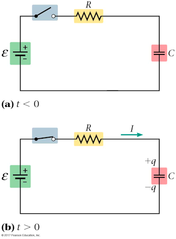
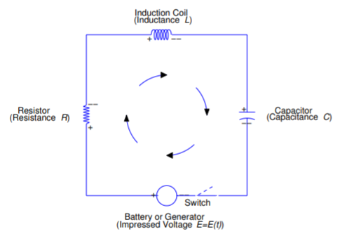
Given the following conditions for a simple electrical circuit, as shown in the diagram below, the capacitance is 1 farad, the inductance is 1 henry and the impressed voltage is V volts at time t. ... Consider the circuit diagram below: Given conditions: ℰ = 400 Volts R = 4000 Ω C ...
A Ω(n 3) depth circuit is required to implement the first-order Trotterized form of this ansatz 63. Hence NIBPs become more prominent for generalized UCC ansatzes. Hence NIBPs become more ...
The circuit diagram in Fig. 3.57 can be used to analyse the interruption of a. capacitive current. The capacitive load is given as CL and is much larger than the. network's capacitance to ground Cn. The current interruption takes place at current. zero crossing.

Let us consider the simplest case of a pair of coupled oscillators, each of resonance frequency ω 0 and interacting via the coupling constant g. The two resulting eigenfrequencies ω 2 and ω 1 ...
the circuit diagram shows the use of a potentiometer to ... Solved: Using The Circuit Shown Below To Calculatea - The E ... 4 Ways to Calculate the Area of a Triangle - wikiHow
An AC circuit has three coils in series. Each coil has aninductance of 80 mH and a resistance of 10 Ω. Calculate: a the totalinductance b the impedance of the circuit at 50 H. Dec 02, 2021. SOLUTION.PDF. SOLUTION.PDF Get Answer To This Question ...

A finite-state machine (FSM) or finite-state automaton (FSA, plural: automata), finite automaton, or simply a state machine, is a mathematical model of computation.It is an abstract machine that can be in exactly one of a finite number of states at any given time. The FSM can change from one state to another in response to some inputs; the change from one state to another is called a transition.
In electronics, negative resistance (NR) is a property of some electrical circuits and devices in which an increase in voltage across the device's terminals results in a decrease in electric current through it.. This is in contrast to an ordinary resistor in which an increase of applied voltage causes a proportional increase in current due to Ohm's law, resulting in a positive resistance.
Non-parametric regression modeling using GP was also performed for this dataset. Scikit-Learn's GP library (Pedregosa et al., 2011) was used with a Matérn kernel (Rasmussen and Williams, 2005) as follows: (6) k M a t é r n (r) = 2 1 − ν Γ (ν) (2 ν r ℓ) ν K ν (2 ν r ℓ) where ν and ℓ (length scale) are the
Rt R1R2R1R2 11 1 1 12 05 ohms. When the two resistors are connected in this way they form a system equivalent to a single resistor of resistance R as shown in the next diagram. Solve for the maximum power that can delivered to R. The figure below shows two resistors R 1 and R 2 connected in series with a battery of emf 12 V.
PDF | Additively manufactured nano-MEH systems are widely used to harvest energy from renewable and sustainable energy sources such as wind, ocean,... | Find, read and cite all the research you ...
The 3 dB coupler and six-port circuit are fabricated and measured with a vector network analyser, Agilent 85058E, and their photographs are shown in Figure 13a,b, respectively. The measured results of this 3 dB coupler and the six-port circuit are shown in Figures 9, 11 and 13, respectively. Due to the influence of SMA connectors and conductor ...

A Nyquist plot is a parametric plot of a frequency response used in automatic control and signal processing.The most common use of Nyquist plots is for assessing the stability of a system with feedback.In Cartesian coordinates, the real part of the transfer function is plotted on the X-axis.The imaginary part is plotted on the Y-axis.The frequency is swept as a parameter, resulting in a plot ...
• The diagram below illustrates the difference between a DC and AC. 11/29/21 23 Fig 2.1: ... Potential Difference • The potential difference between two points in an electric circuit is the work done when a coulomb of charge passes between the points. ... (Ω). 11/29/21 25. 2. Basic electrical measurements contd.
In the circuit diagram is given below resistors R 1, R 2 and R 3 of 5 Ω, 10 Ω and 20 Ω respectively are connected as shown in fig. Calculate: (A) Current through each resistor (B) The total current in the circuit (C) The total resistance in the circuit Solution:
In a space below draw a diagram showing all the elements connected in one electrical circuit that can provide the maximum rate of heat produced. Use two meters in your circuit, the y will help to measure the heat rate. The battery has an emf of 12 V and an internal resistance of 0.5 Ω and each heating 6. The diagram below shows a typical ...


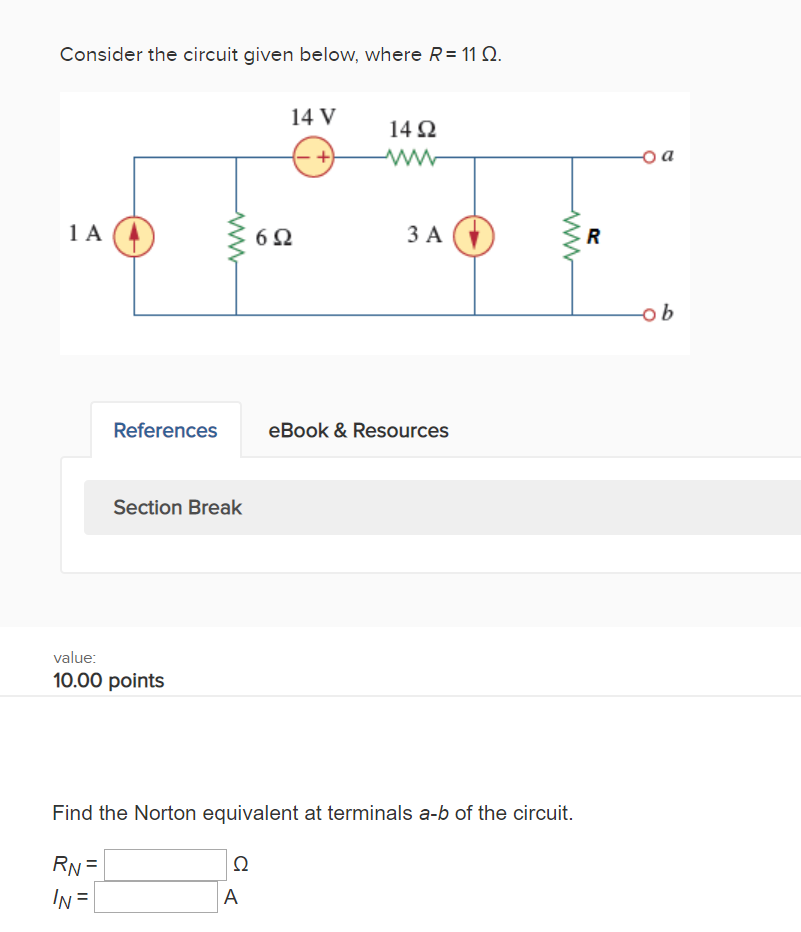


0 Response to "40 consider the circuit in the diagram below, in which r = 11 ω."
Post a Comment