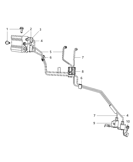
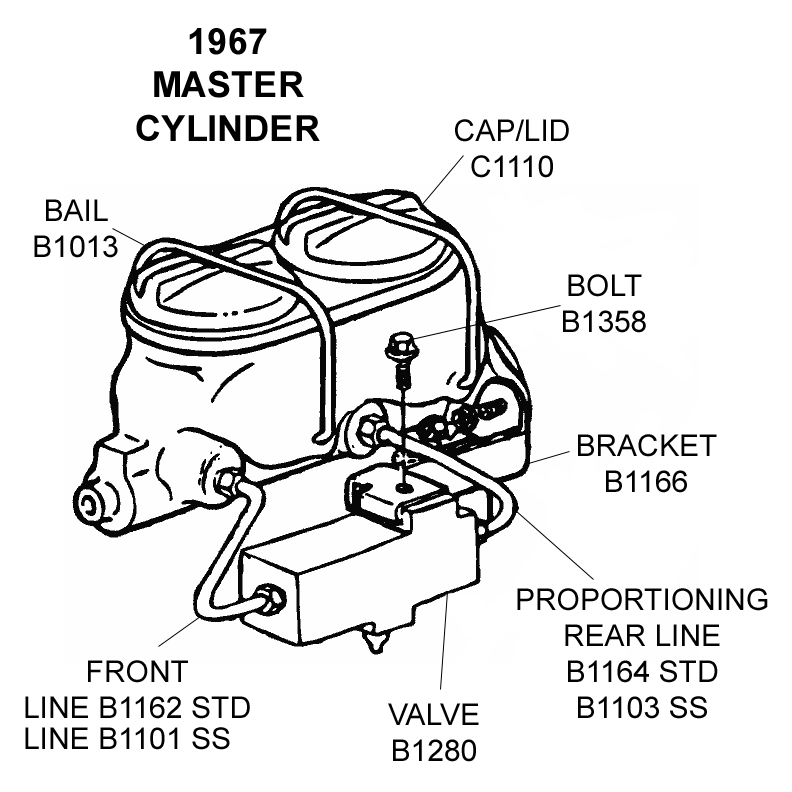
40 master cylinder line diagram
A 7" booster like Speedway part number 91031430, will accept master cylinders designed for a power brake system.They have 3 3/8" center to center mount pattern. Speedway offers a 1" bore GM style master cylinder, typically recommended for front disc/rear drum or four-wheel-disc applications under part number 91031445.We also carry a GM style 1 1/8" bore master cylinder under part number ...
Jul 27, 2016 — The master cylinder establishes the pressure in a brake system; ... When routing flex lines always make sure there is enough slack for full ...
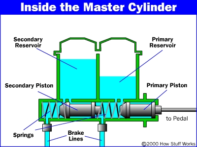
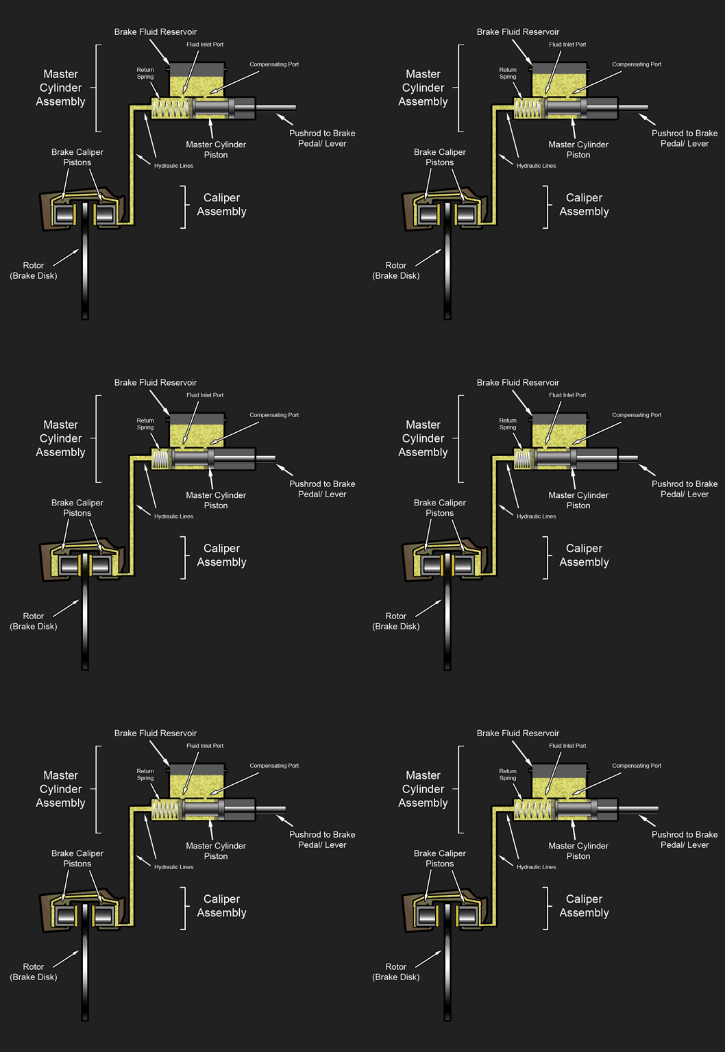
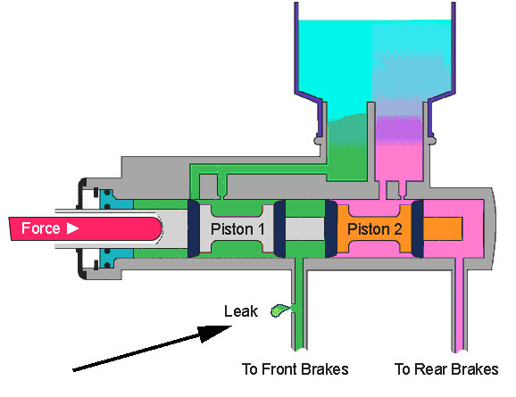
Diagram of master cylinder When the brake pedal is depressed, it pushes on the first (primary piston) through a linkage. The Pressure builds in the cylinder and lines as the brake pedal is depressed further. The pressure between the primary and secondary piston forces the secondary piston to compress the fluid in its circuit.
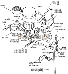
Master cylinder line diagram
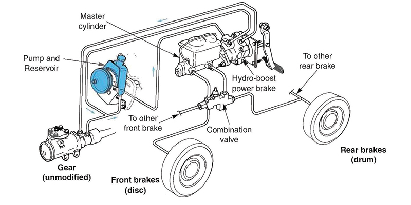
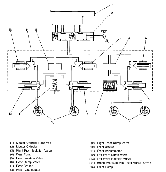
The diagram will show the brake line routing from the master cylinder to each wheel. Brake line diagram. Where do brake lines go to and from abs pump? The diagram shows the brakes in the applied position. Most brake lines are 3/16 diameter. I have the oem jeep shop manual but it does not have a diagram. Did a search and didn't find a diagram ...
Brake line diagram master cylinder Look like the back lines are top on rear sideof master cylinder and bottom of front side, is this correct Posted by richard ernest on Oct 30, 2013
A disc/drum master cylinder requires more fluid vol-ume for the disc brake circuit, so the disc reservoir will be larger. An original disc/drum master cylinder may feature a built-in residual valve for the drum brake circuit. If a replacement disc/drum master cylinder is selected, an ex-ternal residual valve may need to be added. 18 October 2012
Master cylinder line diagram.
May 1, 2012 — 95.5-2004 Tacomas & 96-2002 4Runners - Master Cylinder Lines Diagram - Hey guys: Long time since I posted. I recently had a hard brake pedal ...
This diagram illustrates the 2 most common types of fittings used in street rod brake systems. The first is the inverted flare type, which is used by most domestic production cars and trucks, and on the bottom is the -3 AN (which is pronounced as dash three A N or number three A N).
IN: This end should be placed toward the master cylinder (3/4" hex nut end). Out: This end should be placed toward the brakes (round brass end). 2. Connect brake lines using appropriate brake lines. An installation kit can be purchased separately from JEGS (Part #555-63005). 3.
The primary port on any two port master cylinder is the port closest to the mounting surface. Pressure to the primary (first ) port comes from the primary (first) piston in the master cylinder. The secondary port would therefore be the second port with pressure supplied by the secondary piston.
Diagrams and Schematics Index Section A - Front/Rear Axle Assemblies and Suspension Front Axle Rear Axle Driveshaft Suspension: Wheels Section B - Brake Assemblies and Components Hydraulic Brake System Master Cylinder Brake Booster Clutch/Brake Pedals Section C - Steering Components Steering Column Steering Box Steering Linkage ...
MASTER CYLINDER. At the least in a brake system, change to a dual reservoir master cylinder. The master cylinder needs to match your braking system. Otherwise you can have all sorts of problems. A drum/drum system needs a drum/drum master cylinder, a disc/drum system needs a disc/drum master cylinder, a disc/disc needs a disc/disc master cylinder.
Aug 25, 2006 — INSTALLATION NOTES: •, On Disc front, Drum rear combinations with a single master cylinder, be sure to remove the residual check valve, ...
The valve should be installed on the brake side of the proportioning valve as shown in the diagram. • When using a dual master cylinder with Disc front, Drum rear combinations you won't need to remove the residual check valve as it only applies pressure to the rear brake line.
4WD Rear Drum Brakes 1957-72 F100 F250. Brake Hoses and Brake ...1953-56 F100 F250 F350. Brake Master Cylinder 1960-66 Chevy & GMC Truck. Brake Master Cylinder Cap 1987-13 Ford Full-Size Van. Brake Master Cylinders 1983-94 Ranger 1984-90 Bronco II. Ford 9" Rear Disc Brake ...1980-86 F100 F150 Bronco.
1 answerLOOK INSIDE THE MASTER CYLINDER TAKE COVER OFF THERE IS TWO SECTIONS THE LARGER ONE IS FOR THE FRONT WHEELS AND SMALLER IS FOR REAR WHEELS YOU SHOULD BE ...
Master Cylinder Line Set without Power Brakes - to Proportioning Valve - Front and Rear (stainless. Part #500095. $35.00. Add to Cart. 1974-1982. Steel Master Cylinder Line Set - to Proportioning Valve - with Power Brakes OM (Original Metal) - F. Part #500394. $30.00.
When the master cylinder goes, you may start to notice signs such as a brake pedal that feels mushy, spongy or unresponsive. Even worse, it sinks completely to the floor. If your brake fluid becomes tainted, the rubber seals on the master cylinder have broken and the fluid cannot effectively hold pressure.
Use of the correct master cylinder is first. A master cylinder for disc brakes installed front & rear will have the reservoirs the same size. If your master has one reservoir larger (for the front disc's) than the other (for rear drum's), it is for a disc/drum application and should not be used with 4 wheel disc's.
Note: The master cylinder reservoir on Dave's '73 SB has two chambers and two fluid lines to the master cylinder. Rob's '68 Bug has only one chamber in the reservoir and one fluid line down to the dual master cylinder. Rob was pleased to report that the master cylinder on his '70 Standard Bug is the original, and it seems to be in good shape ...
Diagram Part # 23 Quantity Required: 1. 2000 Polaris 250 Xplorer 4x4 A00AG25CA. CONTROLS - MASTER CYLINDER - BRAKE LINE. ... CONTROLS - MASTER CYLINDER/BRAKE LINE XPRESS 300 W969530 AND XPRESS 400 W96. Diagram Part # 36 Quantity Required: 1. 1996 Polaris 500 Sportsman 4x4 W969244.
Here is something IMPORTANT to consider on that Speedway diagram, it is correct if your master cylinder is mounted on the firewall, but it is incorrect if your cylinder assembly is mounted under the floor. In this configuration, you need to reverse the lines into the master, so the line closest to the mounting point/bracket or the brake booster ...
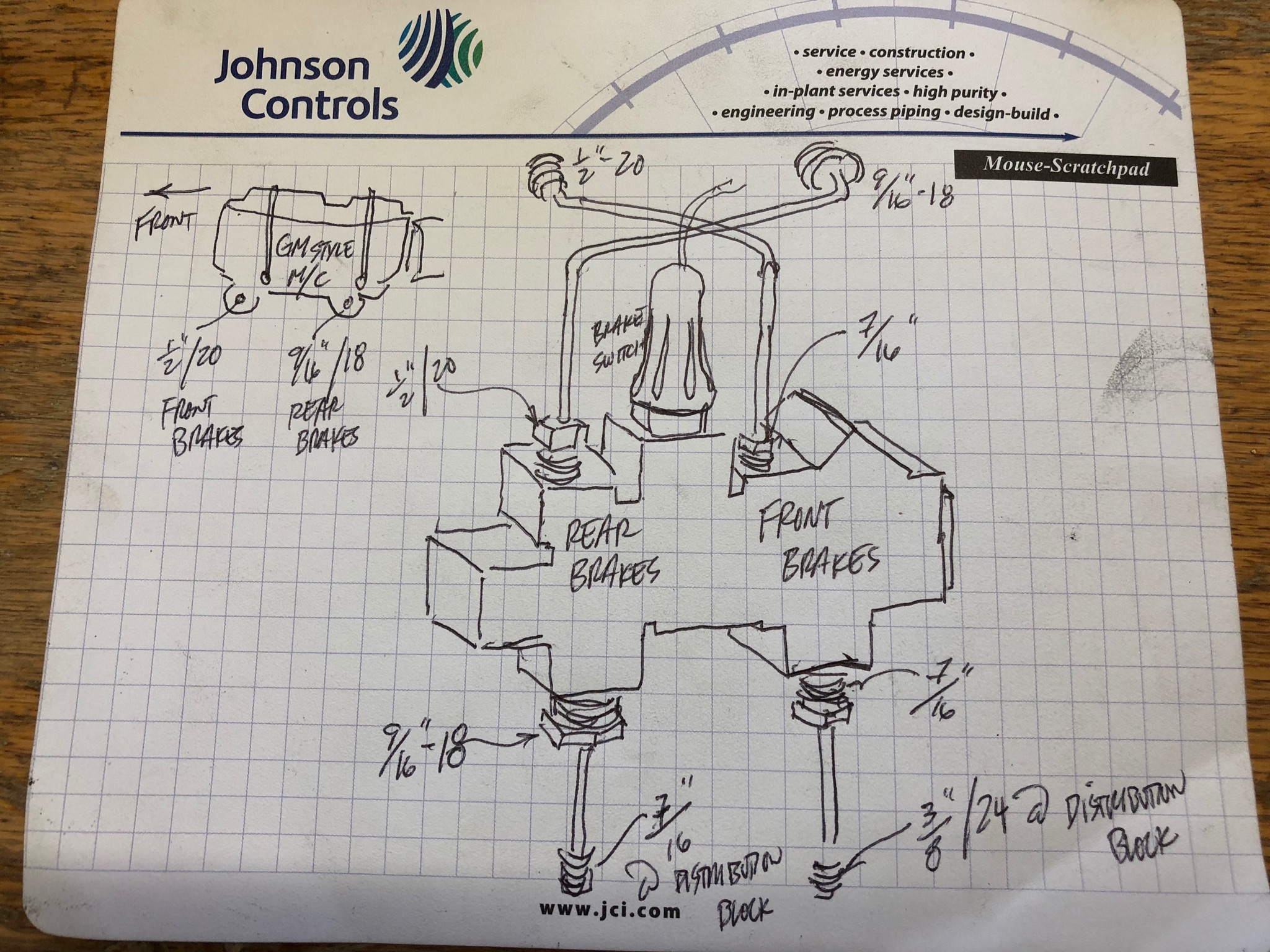
•Each master cylinder kit includes one 9/16-18, one 1/2-20, and two 3/8-24 inverted flare threaded line adapters for connections to the brake lines (Adapters are not installed and are shipped in the reservoir of the master cylinder, remove lid to access).
I ordered a complete brake line set and am now removing all of the brake lines to replace them. One thing I noticed, though. On the ABS master cylinder, the lines don't appear to be connected to the correct channels. I thought that the rear lines would be together on one channel and the front lines would be on the other channel.
Hells Ditch, FL. www.mindspring.com. Jan 3, 2004. #2. kukm66 said: Anyone know of a site for a diagram of a 1967 Mustang showing the master cylinder, coiled brake line to distrubution block and proportioning valve? Specifically, I need to see how the lines are attached in and out.
Jul 15, 2019 — Brake diagram from Master cylinder to booster to lines. Tiny. JUSTIN OSLEY. MEMBER; 2002 PONTIAC GRAND AM; 2.2L; 4 CYL; 2WD; MANUAL ...
Sep 04 2020 1114am. In this video i will show you how to install a brake master cylinder on a 1988 1998 chevy k1500 silverado. When the brakes are applied the master cylinder pressurizes brake fluid through the connected brake lines. The diagram shows 4 connection correct.
If you run your lines in this order there is no crossing or bending of lines necessary. Antilock brake ports: 1. top center port to right front brake. 2. top left port to left front brake. 3. top right port to rear brakes (actually, this line runs in it's own clip. 4. bottom left port to master cylinder rear port.
not necessary to use these as long the lines you are using have a 3/8"-24 fitting already flared on. 2) Connect the front brake outlet of the master cylinder to the port marked "F I" on the top of the Prop Block.The outlet of the master cylinder for the front brakes will typically be the one for the larger reservoir.
Brake Master Cylinder - Function , Working , main parts and Diagram Brake master Cylinders : In automotive engineering, the master cylinder is a control device that converts non-hydraulic pressure (commonly from a driver's foot) into hydraulic pressure. This device controls slave cylinders located at the other end of the hydraulic system.
Master cylinder in an automobile braking system is a hydraulic device in which cylinder and one or two pistons are arranged in such a manner that the mechanical force applied by the driver of a vehicle either by brake pedal (in cars) or by brake lever (in bikes) is converted into hydraulic pressure which in turn transferred to the brake caliper for braking.
in line as close to the master cylinder as possible to prevent fluid drain back. A two pound residual check valve is used for disc brakes and a ten pound is used for drum brakes. An adjustable proportioning valve should be plumed in the rear line to adjust the front to rear brake bias. 9. Install the hydraulic brake lines using 3/16" hard lines.
Joined Aug 21, 2009. ·. 2,069 Posts. Discussion Starter · #1 · Mar 8, 2010. Only show this user. I am searching for the Brakeline Routing Diagram for a 67 CP 289/Auto w/Pwr Disc Brakes. Can anyone supply a copy? My google searches found 65 66 70-72, but no 67 and the search engine here just tries my patience.
Hi, Under the hood is the Master Cylinder. It contains brake fluid, which when you depress the brake pedal, acts as hydraulic fluid to flow through high pressure tubing called brake lines, from the Master Cylinder to the Wheel Cylinder (drum brakes) or Brake Piston Caliper (disc brakes).
2016-07-13 · This diagram shows a typical street rod brake system. A 2 PSI residual pressure valve (RPV) is needed in the disc brake circuit, ...

Chevy impala 2003 brake line set w/ 4 wheel anti lock, w /4 wheel disc brakes 3.4l bl257-ss1d stainless steel set
:max_bytes(150000):strip_icc()/1280px-Master_cylinder_diagram.svg-5a172d594e46ba001a8294ac.png)










0 Response to "40 master cylinder line diagram"
Post a Comment