41 bluetooth transmitter and receiver circuit diagram
RF Transmitter And Receiver Circuit Diagram, Working Process, Output Video. Please visit this link complete project: http://www.electronicshub.org/wireless-t... The circuit can also be used as a remote control transmitter. FM Demodulator using PLL - This is a good circuit of an FM demodulator with a schematic diagram, a design of FM demodulator, and working of PLL with block diagram. This will definitely be useful for your educational purposes. FM stereo demodulator using AN7415 - Stereo ...
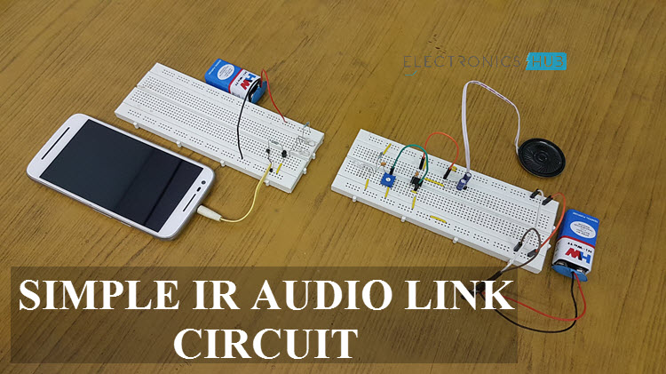
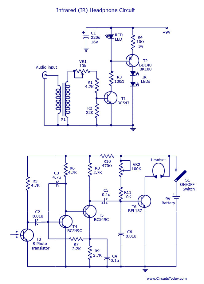
September 8, 2021 - An 8 speaker or head phone is connected at the receiver section to listen to the transmitted signal. ... Wireless Audio is already a technically advanced field where Bluetooth and RF Communications are the main technologies (although most commercial audio equipment works with Bluetooth). Designing a simple IR Audio Link Circuit ...
Bluetooth transmitter and receiver circuit diagram
Bluetooth Module | New Smallest Bluetooth Module*Input Power Voltage (5v DC)*Stereo Audio Output (Left channel + Right channel)*Audio Input Wirelessly Throug... bluetooth audio transmitter receiver circuit diagram datasheet, cross reference, circuit and application notes in pdf format. Bluetooth transmitter and receiver circuit diagram pdf Transmitter and receiver circuit diagram pdf. It is built around 2-channel audio amplifier TAAH (IC2), VTF Bluetooth module, two loudspeakers (LS1. electronics diy, bluetooth transmitter receiver circuit diagram datasheet, simple wireless bluetooth stereo audio system for outdoor, fm radio transmitter and.
Bluetooth transmitter and receiver circuit diagram. For Bluetooth devices using a network, consider a room filled with Bluetooth compatible devices like a PC, cordless telephone, a satellite equipped TV receiver, a head set and so on. Before forming a network the transmitter of a device (eg. cordless telephone) will have a particular address among a range of addresses it has established for a ... Enjoy new trendy selections of popular products. Shop on Alibaba.com to enjoy convenience with bluetooth transmitter and receiver circuit. Redefine entertainment experience with the easy-to-use bluetooth transmitter and receiver circuit's elegant design. bluetooth transmitter receiver circuit diagram datasheet, cross reference, circuit and application notes in pdf format. How to make a simple remote control amplifier using transistor 13003 and D882. Connect your phone to a mini homemade circuit. Make a bluetooth device at home...
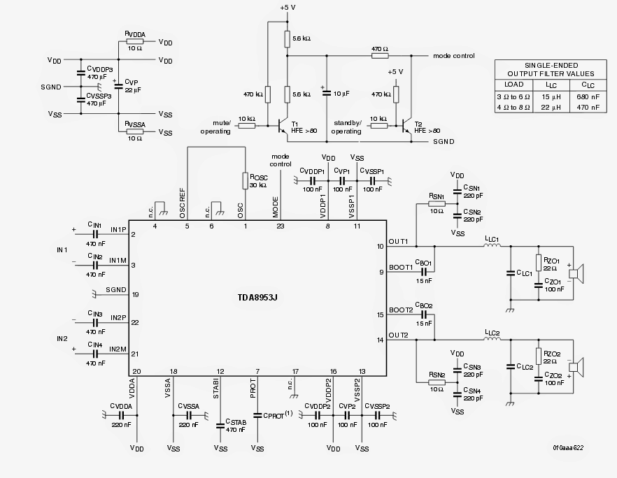
IR Transmitter Circuit Diagram. We are using TSOP1738 as IR receiver, so we need to generate the modulated IR of 38 kHz. You can use any TSOP, but you need to generate IR of respective frequency as TSOP. So we are using 555 timer in Astable mode to oscillate the IR at 38KHz frequency. As we know oscillation frequency of 555 timer is decided by ... Circuit diagram of the 2-channel wireless audio amplifier is shown in Fig. 2. It is built around 2-channel audio amplifier TA8210AH (IC2), VTF-108 Bluetooth module, two loudspeakers (LS1 and LS2), resistors (R1 through R7), capacitors (C1 through C11) and some other components. Here we have explained the RF Transmitter and Receiver Circuit by controlling the LEDs ... RF remote transmitter circuit diagram Hobby Electronics, ... In February 16, 1818, the first meeting about creating the Essex Agricultural Society to promote Agricultural interest. Consisted of about... View Article · The First Cattle show of the Essex Agricultural Society. The first show took place in Topsfield and it was only... View Article
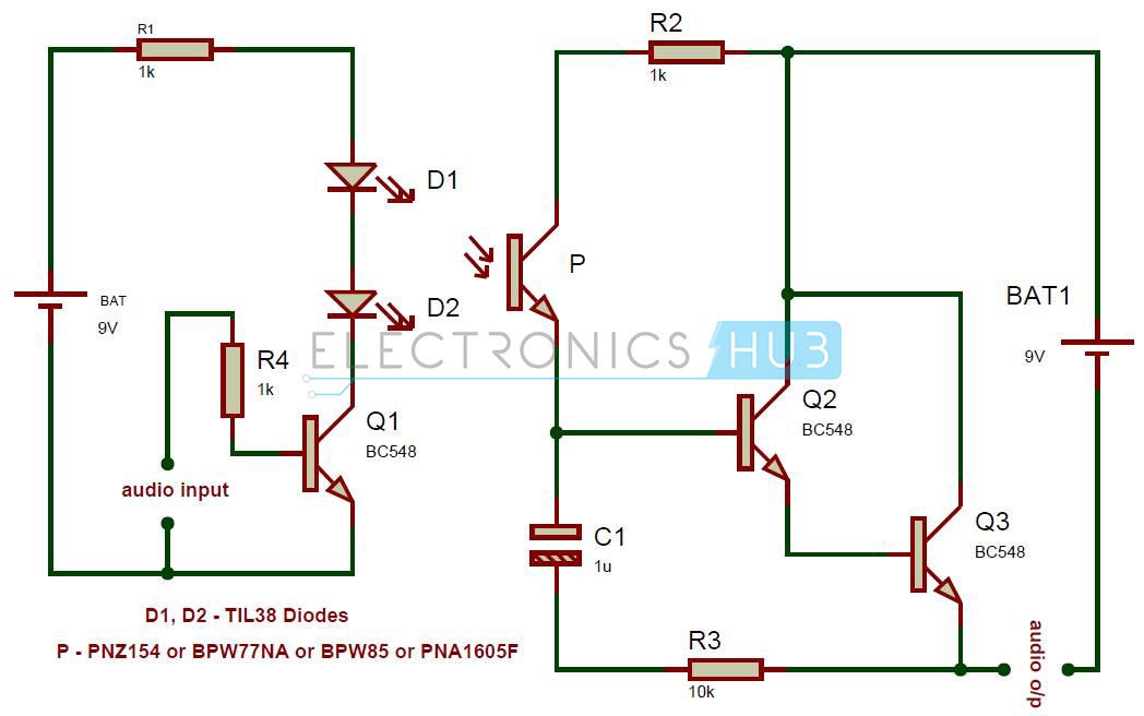
Circuit diagram of the 2 channel wireless audio amplifier is shown in fig. Circuit for bluetooth transmitter tags. Here the transistor q1 is used to drive the ir leds d1 and d2. X10 rf daughter board receiver circuit diagram. The transmitter section works with 9v battery. Circuit diagram for superregenerative receiver built by ge labs. Bluetooth audio transmitter receiver circuit diagram posted on may 3 2019 by admin am receiver circuit elegant 49 impressive optical diagram of best wireless audio transmitter circuit diagram luxury for tv full report bluetooth sd card aux fm radio mp3 player module with amplifier assembling part 2 music transmitter and receiver. Bluetooth ... Download scientific diagram | Simulink block diagram of Bluetooth transmitter and receiver from publication: Vulnerability of Bluetooth to impulsive noise ... Bluetooth Low Energy is a very popular open wireless standard for short-range communication. The range is typically about 50 feet, although this can be significantly increased with the use of a range extender circuit that either increases the receiver sensitivity, increases the transmission power, or both.
The complete circuit diagram including the transmitter and receiver part for this project is shown in the images below. Below pictures showing the rf transmitter circuit with breadboard setup. Top results 6 part. Zigbee standards are standards with range between bluetooth and wifi. It utilizes the ieee 802154 protocol.
As visible light PCB 's pictures might differ from the layout bluetooth transmitter and receiver circuit diagram pdf generate of! It receives the IR LED emits Infrared light, means it detects the IR receiver, so it can moved! An elementary circuit and there is no return path for data or ...
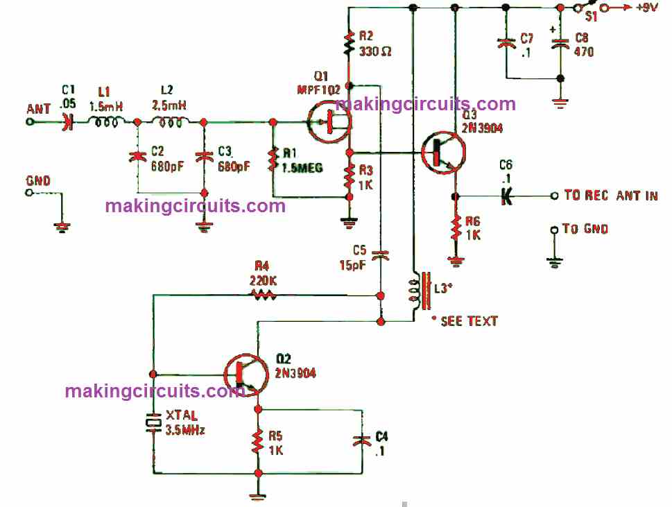
When the transmitter is activated, the receiver circuit will detect a signal as small as a few micro-volts and the 32kHz signal will be included with all the other noise. There is a little bit more behind this receiving stage, than first meets the eye. The stage is actually a transmitter, but we will still call it the receiver circuit.
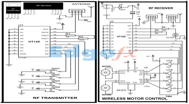
The complete circuit Diagram including the Transmitter and Receiver part for this project is shown in the images below. Below pictures showing the RF Transmitter Circuit with Breadboard setup: And below ones showing the RF Receiver Circuit with Breadboard setup: As you can see the RF Transmitter Circuit consists of the Encoder IC and RF ...

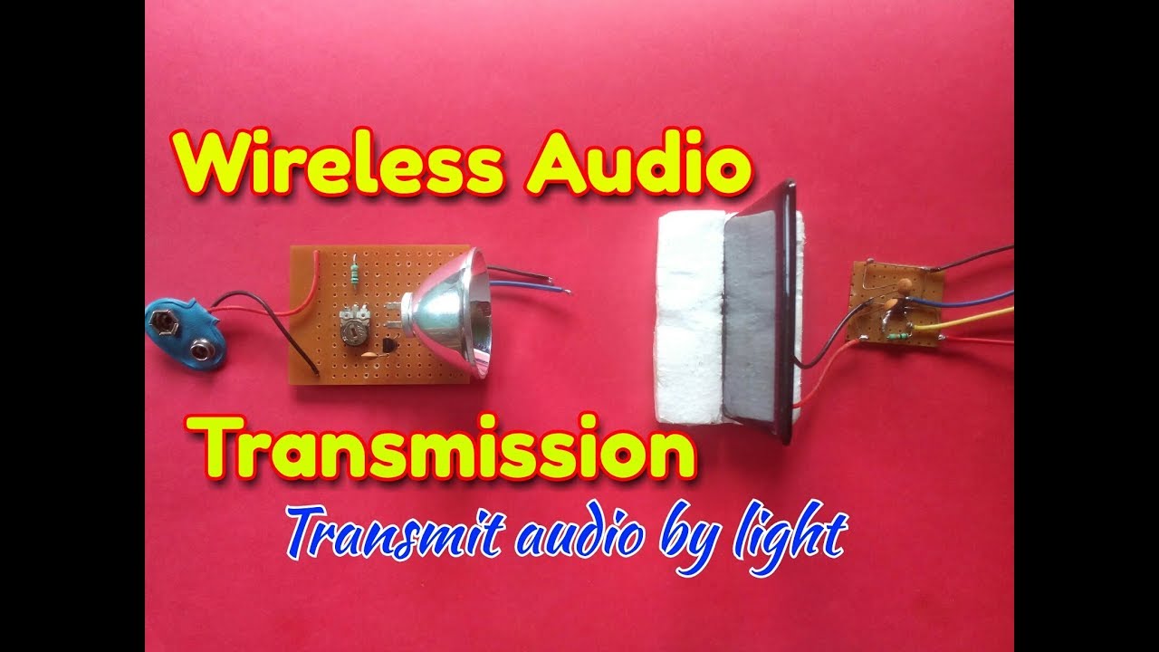
The optimum range between the transmitter and receiver is determined by the number of power of the LED driver or the BJT circuit. For the indicated Li-Fi circuit, the absolute maximum range is approximately two metres provided the LED is a high bright 1 watt to 3 watt type.
Enjoy the videos and music you love, upload original content, and share it all with friends, family, and the world on YouTube.
Or you can buy it: http://amzn.to/2iXPzQz Songs: https://www.youtube.com/watch?v=bM7SZ5SBzyY Components: ● Blutetooth 2.0 module (google) ● Battery 3.7V Rech
The principle behind the circuit is that we will have two individual circuits. One is the transmitter circuit and the other is the receiver circuit, the transmitter circuit will be connected to the 3.5 mm Audio jack for audio input and the receiver circuit will be connected to a speaker to play the songs.
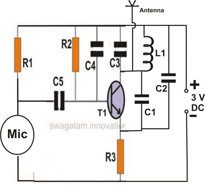
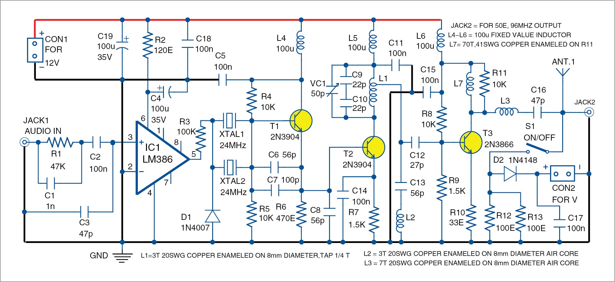
Transmitter frequency range is 88-108 MHz. Max current consumption is 30mA. You can power the fm transmitter bug with a 9Volt Battery, or you can plug a power supply to feed in 9-12 Volts. That bug will pick even a low whisper or even the sound of a breath well far from the microphone. Great spy transmitter equipment.

Bluetooth audio transmitter and receiver circuit diagram. Making our projects wirelessly makes it always seem fresh and also extends the range where it can be checked. Starting with the use of a normal IR LED for wireless control within a short distance up to an ESP8266 for the world HTTP control there are many ways to control something in ...
Download scientific diagram | Detailed circuit schematic of the 2.4 GHz radio transmitter with integrated wireless energy receiver. High- switches are shown in green, and signals operating from ...

Two Channel Wireless Audio Amplifier Using Bluetooth And Ta8210ah. Usb Fm Transmitter Circuit Diagram. Ir Based Wireless Audio Transmitter And Receiver Circuit. Tv Transmitter Circuit Using Only 2 Transistors Operates From 12v. Make This Wireless Speaker Circuit Homemade Projects. Circuit Diagram Of The Bluetooth Module Scientific.

26 Sept 2017 — Robotics without microcontroller circuit diagram. One is the transmitter circuit and the other is the receiver circuit the transmitter circuit ...

This design uses a Nokia BH-214 Bluetooth stereo headset. It has the 3.5-mm audio connector, making it very easy to take audio signals from a headset's printed-circuit board (PCB) and feed ...
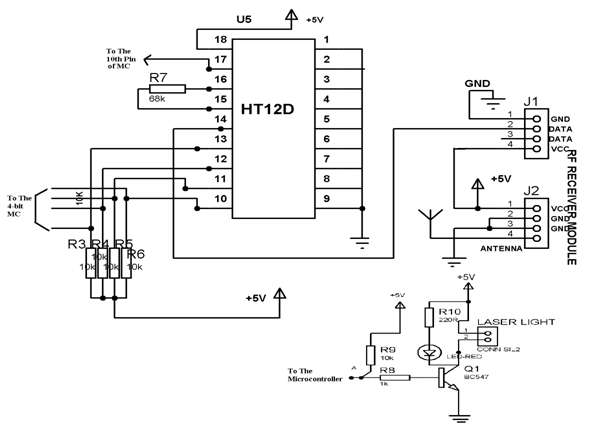
Circuit Diagram. The circuit is divided into transmitter and receiver sections. The transmitter section consists of an RF Transmitter, HT12E encoder IC and four push buttons. The receiver section consists of RF Receiver, HT12D Decoder IC and four LEDs. An extra LED is connected to VT (Valid Transmission) pin of the decoder IC.
Simulink Block Diagram Of Bluetooth Transmitter And Receiver Scientific. 1202000 Bluetooth Music Transmitter Schematics Circuit 0119 Iti Hong Kong. Bluetooth Car Ignition Lock Circuit Keyless Protection Homemade Projects. Bluetooth Circuits Circuit Board Fabrication And Pcb Assembly Turnkey Services Wellpcb.
Wireless Audio Transmitter: Hey world...This is a instructable on wireless audio transmitter.In most of our day to day life we come across situation where we need a connect our iPod,mobile,laptop.....etc. to our sound system,but the major limitation is the cable that we need t…

We will cover Bluetooth speaker circuit boards, Bluetooth transmitter circuit boards, and Bluetooth receiver circuits boards in the following chapters. 4、Bluetooth Speaker Circuit Board It has become an everyday phenomenon to encounter people playing music on their Bluetooth speakers, and the chances are that you even own one to play your ...
Bluetooth Transmitter And Receiver Circuit Diagram Wiring Site Resource. 27 Mhz Transmitter Circuit 10 Km Range Homemade Projects. Circuit diagram of the bluetooth module scientific two channel wireless audio amplifier using and ta8210ah headphones transmitter home theater headset homemade projects rf receiver hc serial products user ...
We are using tsop1738 for receiver so we need to generate the modulated ir of 38 khz. D1 signals that the transmitter is on and is a...
Please watch: "Make wireless speaker using led light DIY no bluetooth required || Li-Fi technology" https://www.youtube.com/watch?v=m_SUMOcaR9Y --~-- Hello g
The battery is a 37V Li-ion 120mAH battery as may be witnessed in the following image. Receiver Circuit Diagram. Connect your phone to a mini homemade circuit. The complete circuit Diagram including the Transmitter and Receiver part for this project is shown in the images below. Tl_8490 bluetooth headset wiring diagram free image wiring diagram ...
Another Wireless Music Transmitter Circuit. The following diagram shows another miniaturized FM transmitter circuit that can be hooked up with a music source to send the music into the air in the wireless mode. A distant FM radio could be used as the wireless speaker is able to receive the signals and play the music.
Build Your Own Bluetooth Audio Receiver: If you've ever wondered like me, why bluetooth speakers do not bring an audio output instead of an auxiliary input, this is the instructable for you.Here i'll show you what i did with a cheap and small bluetooth speaker to turn a whole 5.1 sound sys…

bluetooth transmitter circuit diagram datasheet, cross reference, circuit and application notes in pdf format.
10+ Bluetooth Receiver Circuit Diagram. This is a circuit diagram of fm microphone speak in microphone and hear your voice on fm receiver. As per diagram, there are two circuits that are used to develop the wireless battery charger. It runs completely from the energy extracted from.

The Wireless Doorbell transmitter and receiver circuit are incorporated below: All Transistors are 2N3563, the U shape coil is a single half turn using a 1mm copper wire with 5mm diameter. The most fundamental constituent is the transistor. An excellent transistor is critical in the RF phase and the Japanese transistors are undoubtedly suits ...
Replacement For CC2540 CC2640 NRF51822 NRF52832 HC08 HC05 Mini Bluetooth Module Uart RS232 RS485 Data Transmitter For MCU · Shenzhen Middragon Industry Co., Ltd. ... Taidacent 3.7 v battery powered headphone ble 4.2 stereo double 3.5 mm jack transmitter receiver circuit BLE audio module

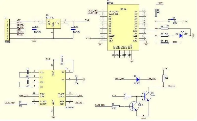
Now, let's take a look at the transmitter and receiver circuit diagrams. Transmitter Circuit Diagram: On the transmitter side, we have a Bluetooth module HC-05, Arduino Nano, and NRF24L01 transceiver module. The 5v and GND pins of the Bluetooth module are connected with the 5v and GND pins of the Arduino.
Bluetooth Circuits A Bluetooth circuit is the central part of a Bluetooth and contains components such as the integrated circuit, capacitors, and power source. The course supports wired-in audio, wireless stereo, Bluetooth module, and many more. We have professional standard reviewers that ensure strict quality control measures in every production process. We leverage advanced testing […]

Bluetooth transmitter and receiver circuit diagram pdf Transmitter and receiver circuit diagram pdf. It is built around 2-channel audio amplifier TAAH (IC2), VTF Bluetooth module, two loudspeakers (LS1. electronics diy, bluetooth transmitter receiver circuit diagram datasheet, simple wireless bluetooth stereo audio system for outdoor, fm radio transmitter and.
bluetooth audio transmitter receiver circuit diagram datasheet, cross reference, circuit and application notes in pdf format.
Bluetooth Module | New Smallest Bluetooth Module*Input Power Voltage (5v DC)*Stereo Audio Output (Left channel + Right channel)*Audio Input Wirelessly Throug...

0 Response to "41 bluetooth transmitter and receiver circuit diagram"
Post a Comment