41 shear moment diagram examples
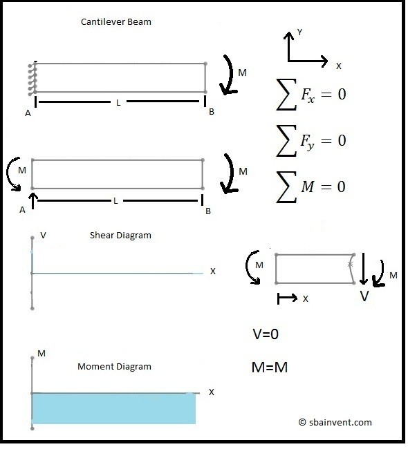
How to solve the conjugate beam: Here are the steps used to solve the conjugate beam from the real beam. Step 1: Find the reactions of the conjugate beam using equilibrium conditions. Step 2: Construct the shear force diagram for the conjugate beam. Step 3: Construct the bending moment diagram for the conjugate beam. Step 4: The values of the shear force in the conjugate beam diagram give the ... Cantilever Beam Point Load And Bending Moment At End. Cantilever Pare. Leaf Spring Calculator. Cantilever Beam Loaded By A Bending Moment At Its End As Seen From Scientific Diagram. Solved Q1 Draw The Shear Force And Bending Moment Diagrams Chegg. Cantilever Beam Uniformly Distributed Load.
Learn structural analysis/ statics of civil engineering structures : Truss, Beam and Frame with practical examples. What you'll learn Concept of Force and Moment Basic Terms used in structural analysis Structural Analysis of all kinds of trusses.. Structural Analysis of all kinds of beams.. Draw Shear Force and Bending Moment Diagrams of Beam.
Shear moment diagram examples
Beam formulas with shear and mom solved 1 draw the shear force and bending moment diagrams chegg how to calculate the bending moment on a continuous beam carrying point load quora mechanics of materials chapter 4 shear and moment in beams bending moment curves in a continuous beam scientific diagram. Sfd and bmd examples.Use equilibrium conditions at all sections to. Get the unknown sf and bm. Find the internal torques at points b and c of the circular shaft subjected to three concentrated torques solution: Shear force diagram (sfd) & bending moment diagram (bmd) form the basis for design of beams in general. Axial force diagrams come additionally for column design. 0 ratings0% found this ... Use of shear force and bending moment diagrams. Different uses of ( SF ) \text {and} ( BM ) diagrams are as follows -. Shear force and bending moment diagrams are analytical tools. These diagrams are used in designing of structural members along with use of structural analysis to find out the critical sections under severe stress conditions.
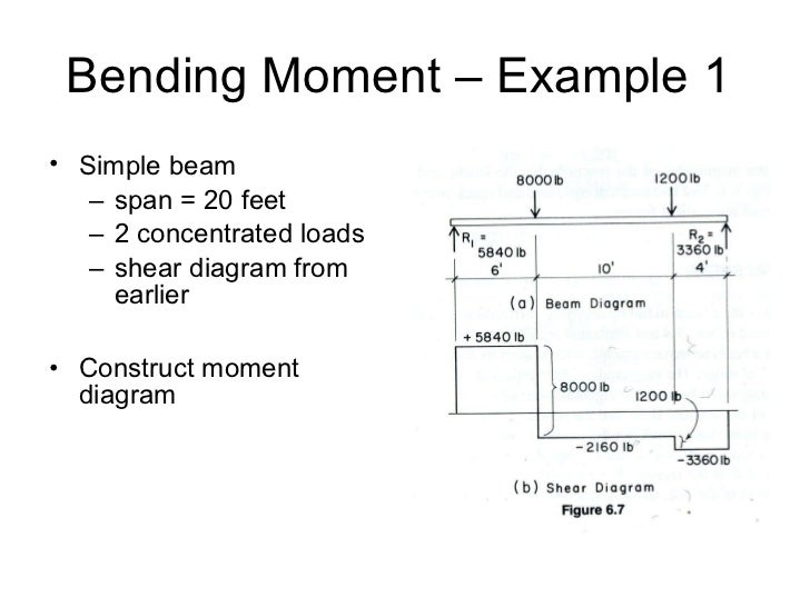
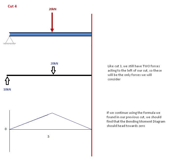
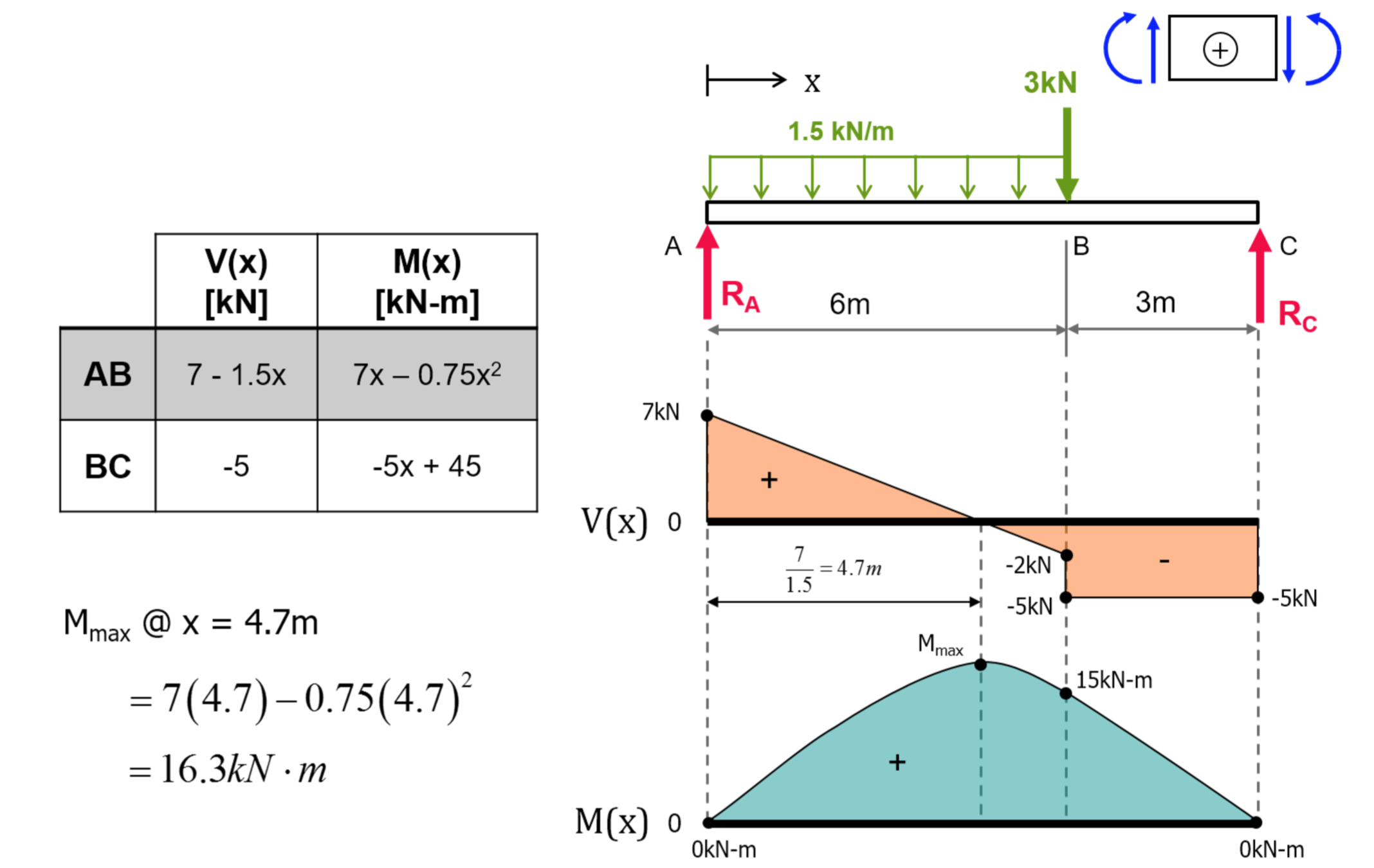
Shear moment diagram examples. Once you have the reactions, draw your Free Body Diagram and Shear Force Diagram underneath the beam. Finally calculating the moments can be done in the following steps: 2. From left to right, make "cuts" before and after each reaction/load. To calculate the bending moment of a beam, we must work in the same way we did for the Shear Force ... Calculating Shear Force Diagram - Step 2: Keep moving across the beam, stopping at every load that acts on the beam. When you get to a load, add to the Shear Force Diagram by the amount of the force. In this case we have come to a negative 20kN force, so we will minus 20kN from the existing 10kN. i.e. 10kN - 20kN = -10kN. Shear and Moment Diagram Example 3 - Mechanics of ... Calculate the maximum and minimum shear and bending moment and various critical locations. According to calculus, it comes in the knowledge that a point load will conduct to a continuously differing moment diagram, and an unvarying distributed load will lead to a quadratic moment diagram. Shear And Moment Diagram Force Portal Frame Bending Png Clipart Angle Architectural Engineering Area. 21 b example 18 for the given frame in 22 a draw normal shear scientific diagram a draw the normal force shear and bending moment diagrams for shown frame is pin hinged connected at c d there rigid joint draw the shear force and bending moment ...
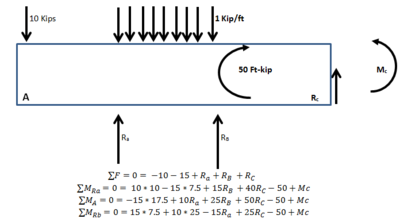
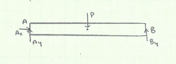
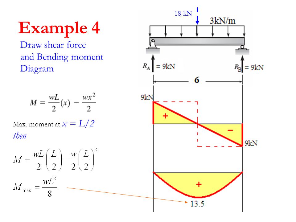
Bending moment diagram simply supported beam formulas with shear and mom a cantilever beam ab supports couple draw shear force diagrams for the image text draw the shear and moment. Use this beam span calculator to determine the reactions at the supports draw the shear and moment diagram for the beam and calculate the deflection of a steel or ... Draw Shear Force Diagram. Find location of Zero Shear force. Find the Maximum Moment. Draw the Moment Diagram. M (k-ft). A.13 pages Level 1: Single Point Load. This is example shows how to use the steps outlined in the "Steps" tab to draw shear force and bending moment diagrams. Shear force at a cross section of beam is the sum of all the vertical forces either at the left side or at the right side of that cross section.. Bending moment at a cross section of beam is the sum of all the moments either at the left side or at the right side of that cross section.. Types of Rigid Supports. Simple Supports. Roller Support; Hinge Support (or) Pin Support
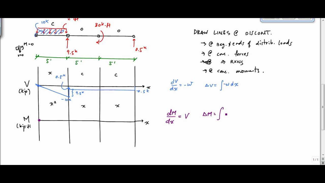
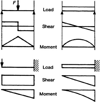
Shear force and bending moment diagrams. Example 11.2 Using the slope-deflection method, determine the end moments and the reactions at the supports of the beam shown in Figure 11.8a , and draw the shearing force and the bending moment diagrams. Shear Diagram. Moment Diagram. 1. Point loads cause a vertical jump in the shear diagram. The direction of the jump is the same as the sign of the point load. 2. Udl result in a straight, sloped line on the shear diagram. 3. The shear diagram is horizontal for distances along the beam with no applied load. Consider the shear force between A and D for example; it's constant, which means the slope of the bending moment diagram is also constant (an inclined straight line). Example 1. A simply supported beam is loaded as shown in the diagram. Calculate the support reactions and draw the Bending Moment diagram, Shear Force Diagram, Axial Force Diagram. Answer (1 of 2): If you are asking how software like Ansys computes the maximum bending moment and shear force. I would say that it depends on the type of element you choose for your skeletal structure. Actually, in finite elements, there is no difference in how you treat bending and torsional mo...
The end result is these moment, shear, and deflection plots (a 4.0m beam with 2.34m cantilever with some random loads):- Loads are entered in a format of load and location arrays similar to shown below for UDL's and point loads on main span and cantilever (if required), these form the inputs for the overarching BEAM_analysis function.
the shear force diagram; the bending moment diagram; the deformed shape of the beam. At this stage, to be able to plot the expressions, all the parameters of the problem must be substituted by numerical values, with the natural exception of the x variable, since this is the independent variable.

Diagrams. Shear force and bending moment are examples of interanl forces that ... A bending moment diagram is one which shows variation in bending moment ...9 pages
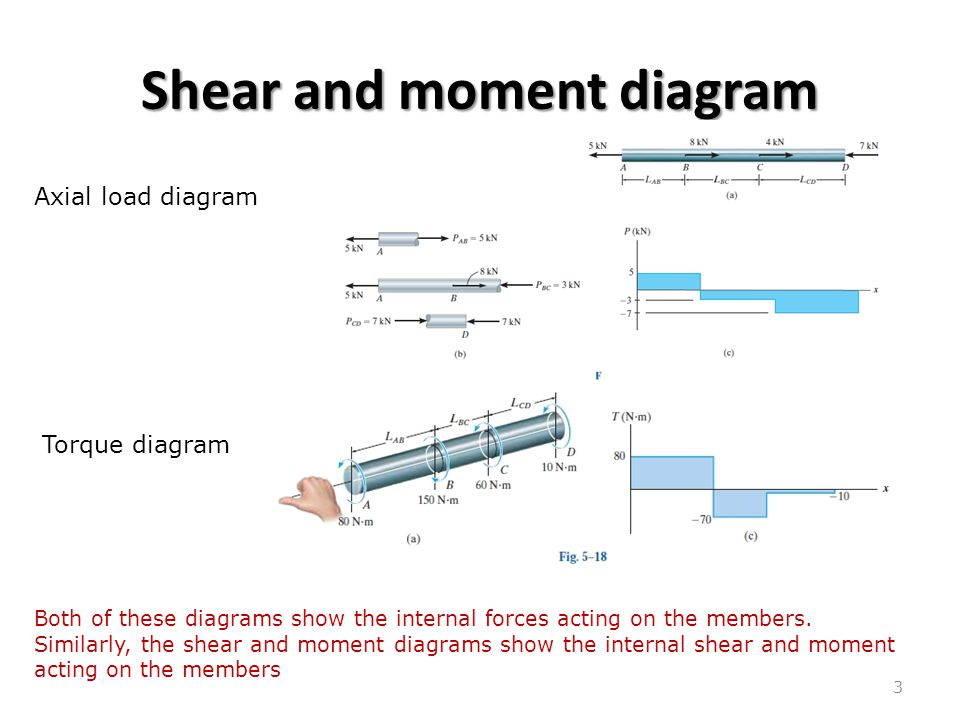
The bending moment diagram, or BMD in short, is a diagram plotted on-top the structure, that displays the value of the bending moment at any point. Similarly the shear force diagram, or SFD, displays the value of shear force at any point of the structure while the axial force diagram, or AFD, displays the value of the axial force.

9.1 Draw the influence line for the shear force and moment at a section n at the midspan of the simply supported beam shown in Figure P9.1. Fig. P9.1. Simply supported beam. 9.2 Draw the influence lines for the reaction at A and B and the shear and the bending moment at point C of the beam with overhanging ends, as shown in Figure P9.2. Fig. P9.2.

Draw The Shear And Moment Diagrams For The Beam Chegg - Draw the shear and moment diagrams for the beam chegg discountpapers.web.fc2.com. Shear forces and bending moments. Solved for the simply supported beam shown below a dra chegg. Determine the reactions and draw the shear and bending. 63 sfd bmd 30kn 10kn 50kn parabola x = 1.5 m parabola 20knm 10knm point of contra flexure bmd cubic ...
4.0 Building Shear and Moment Diagrams. In the last section we worked out how to evaluate the internal shear force and bending moment at a discrete location using imaginary cuts. But to draw a shear force and bending moment diagram, we need to know how these values change across the structure.
Graphs are used to describe the change of shear forces and moments. These graphs are called shear and moment diagrams. Employing these diagrams, the maximum and ...

Shear Force And Bending Moment Diagram Examples For Frames. reza July 27, 2021. Frame in 22 a draw the normal shear bending moment diagrams of portal shear and moment diagrams of a frame shear and bending moment diagrams for. 21 B Example 18 For The Given Frame In 22 A Draw Normal Shear Scientific Diagram.

Creation of the Shear/Moment Diagram Finally, we can calculate the shear/moment diagram! As discussed previously, we can use a few extra rows of nodes to ensure all the critical nodes are included. This is set as nodes_tol=25.0 inches, which corresponds to about 2 rows of elements. As this model is fairly uniform in side, this is adequate.
This program calculates the shear force and bending moment profiles, draw. the free body, shear force and bending moment diagrams of the problem. Under the free body diagram, the equations of each section is clearly. written with Latex. To use this program, you call the function placing the arguments in cells.

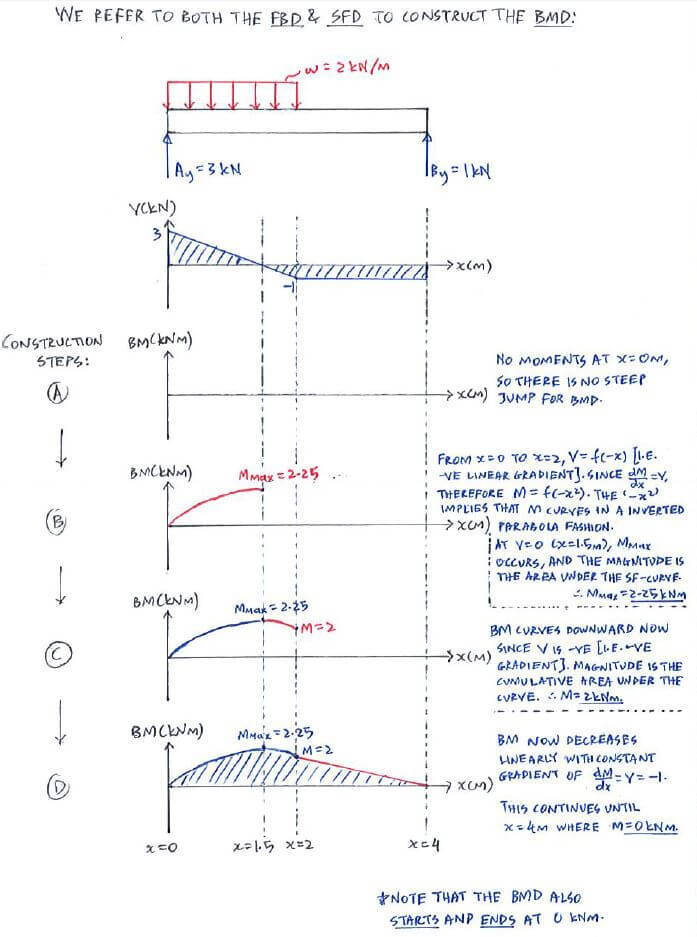
Bending Moment Diagram of cubic or third degree curve for the portion over which uniformly varying load is acting. Bending Moment Diagram consists of fourth degree curve if the load distribution is parabolic. Bending Moment is maximum where shear force is zero or changes sign. Bending Moment abruptly at the point of application of couple.

Our shear force and bending moment diagram calculator simply repeats the analysis described above for every load type and adds all of the shear force and bending moment diagrams together. Fig. 8: Superposition of shear force diagrams for point load (A), point moment (B) and linearly varying distributed load (C) to produce the final shear force ...
Apr 28, 2019 — Being able to draw shear force diagrams (SFD) and bending moment diagrams (BMD) is a critical skill for any student studying statics, ...

❑The weight of the beam is an example of distributed loading, but ... 4.3 Shear- Moment Equations and Shear-Moment Diagrams. ❑ The determination of the ...42 pages
The calculated shear and bending moments of a beam are almost always shown graphically as a diagram. So it important to know how to draw bending moment and shear force diagrams as an engineer, as you will likely to be asked if you apply for a mechanical or structural engineering role.

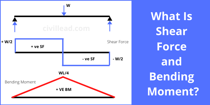
Shear Force Diagram (SFD) Shear Force Diagram of Beam Now let's see how shear force varies along a concrete beam loaded with uniform load 'w' and supported on points A and B. Assuming the beam to be massless, if we write the equilibrium equations along vertical direction, we will get the support reactions 'Va' and 'Vb' as WL / 2.
Use of shear force and bending moment diagrams. Different uses of ( SF ) \text {and} ( BM ) diagrams are as follows -. Shear force and bending moment diagrams are analytical tools. These diagrams are used in designing of structural members along with use of structural analysis to find out the critical sections under severe stress conditions.

Sfd and bmd examples.Use equilibrium conditions at all sections to. Get the unknown sf and bm. Find the internal torques at points b and c of the circular shaft subjected to three concentrated torques solution: Shear force diagram (sfd) & bending moment diagram (bmd) form the basis for design of beams in general. Axial force diagrams come additionally for column design. 0 ratings0% found this ...

Beam formulas with shear and mom solved 1 draw the shear force and bending moment diagrams chegg how to calculate the bending moment on a continuous beam carrying point load quora mechanics of materials chapter 4 shear and moment in beams bending moment curves in a continuous beam scientific diagram.


0 Response to "41 shear moment diagram examples"
Post a Comment