41 submersible pump wiring diagram
Please see more wiring amber you can see it in the gallery below. Thanks for visiting our website to search Submersible Pump Control Box Wiring. . Hopefully we provide this is often ideal for you. sy 5317] pump control panel wiring diagram franklin 4 3 wire control box 2 hp 220v 50hz 1ph e herms brewery build forum - skrilnetz 3 4 hp goulds ...
Water Source Submersible Well Pump Wire Compression Splice Kit-Sk320 - Submersible Well Pump Wiring Diagram. Wiring Diagram consists of several detailed illustrations that present the link of varied products. It contains guidelines and diagrams for different kinds of wiring techniques as well as other products like lights, windows, and so on.
3 Wire Well Pump Wiring Diagram - 3 wire submersible well pump wiring diagram, 3 wire well pump control box wiring diagram, 3 wire well pump wiring diagram, Every electric arrangement is made up of various distinct pieces. Each part ought to be placed and connected with different parts in specific way. Otherwise, the structure won't work as it should be.
Submersible pump wiring diagram
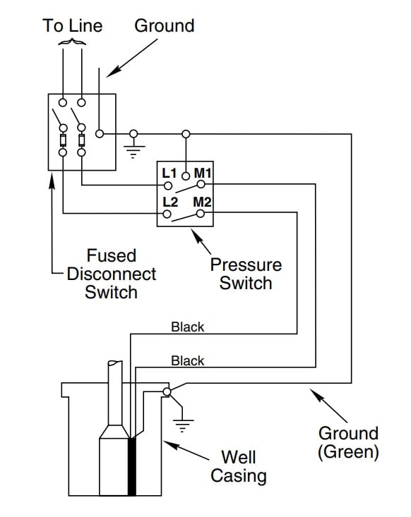
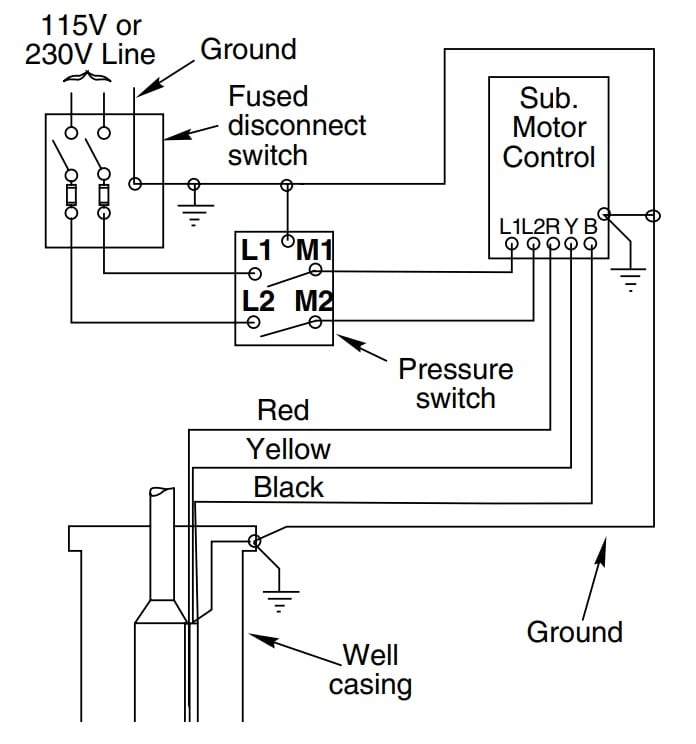
Deep submersible well pumps will be either 2-wire or 3-wire well pumps, and 3-wire well pumps will need a separately installed control box. Two-Wire Well Pump Wiring Diagrams 2-wire well pump diagrams are slightly easier to understand, and are more straight-forward to wire.
Submersible pump wiring diagram control panel pumping station pumps electronics electrical wires cable engineering png pngwing aim manual page 54 single phase motors and controls motor maintenance north america water franklin electric microcontroller three power 1000x648px circuit breaker for molock pumpset starter magnum controller compact is a powerful controlling device your made with hea ...
3 phase solar submersible pump inverter circuit homemade projects how to wire the mppt controller with and panels rison manufacturer of full range pumping system diagram shows pv changeover switch poster id 63037759 for hot water 1100w 110v dc com schematic driven scientific wiring grand technologies ltd facebook panel diffeial proposed installation instructions pumps user manual sps spc ...
Submersible pump wiring diagram.
Please download these submersible pump control box wiring diagram by using the download button, or right click selected image, then use Save Image menu. What is a Wiring Diagram? A wiring diagram is an easy visual representation in the physical connections and physical layout of an electrical system or circuit.
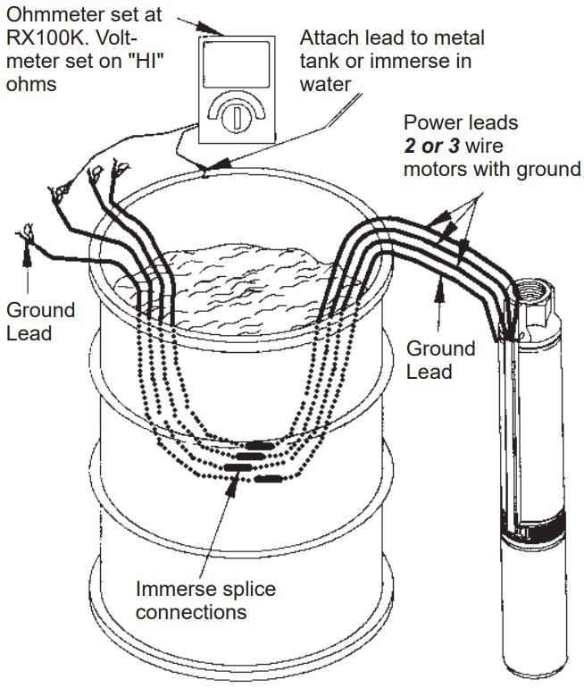
pump. This will center the pump in the well and keep the pipe from twisting due to torque created by the pump motor. 13. IMPORTANT! Wire splices should be staggered, securely crimped and weatherproof. Heat shrink splice kits have a sealant that makes the joint completely waterproof. 14. Pump should be suspended some distance off the bottom
3 Phase Submersible Pump Wiring Diagram from i2.wp.com. To properly read a wiring diagram, one provides to find out how the components inside the method operate. For instance , in case a module is usually powered up and it sends out a signal of 50 percent the voltage plus the technician does not know this, he would think he offers an issue, as ...
submersible pump wiring diagram - What's Wiring Diagram? A wiring diagram is a type of schematic which uses abstract pictorial symbols to show each of the interconnections of components in a very system.
Submersible Pump Float Switch Wiring Diagram - wiring diagram is a simplified customary pictorial representation of an electrical circuit. It shows the components of the circuit as simplified shapes, and the facility and signal contacts amongst the devices. 2 Wire Submersible Well Pump Wiring Diagram Wiring
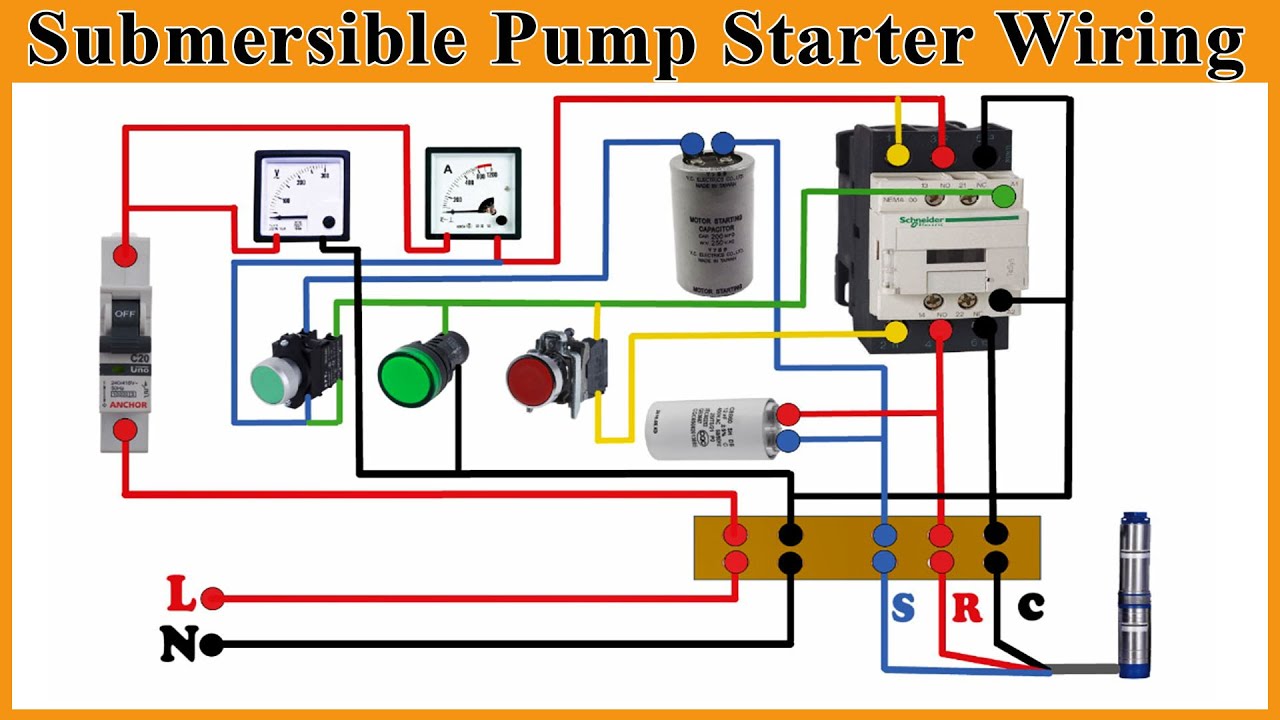
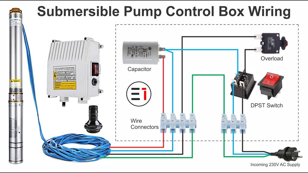
In submersible motor we use wire connectors, DPST switch (double pole single throw) , capacitor and reset able thermal overload protector. From the switch we can switch on or off the motor , and reset able thermal overload protect our motor during high current flow. Here is the complete diagram of single phase submersible pump starter wiring ...
The wiring connection of submersible pump control box is very simple. 220v 3 wire well pump wiring diagram. Red and yellow might indicate that it is a 2 wire 220 volt pump. 2 wire well pump diagrams are slightly easier to understand and are more straight forward to wire.
Pressure Switch Wiring Diagram Air Compressor On 5 Gif Cool And Ingersoll Rand On Ingersoll Air Compressor Pressure Switch Air Compressor Air Compressor Switch Wiring Diagram For 220 Volt Submersible Pump Submersible Pump 1993 Ford Mustang Wiring Diagram 2001 Ford Mus Submersible Pump Submersible Well Pump Sump Pump How To Wire Contactor And Overload Relay […]
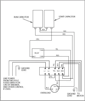
Typical 4-wire submersible pump control box wiring diagram These4-wire well pump wiring connections are typical for a single-phase submersible pump. GREEN = ground BLUE = run BROWN = start BLACK = common You will see that
Wiring diagram of a submirsve pump with a floater switch. A wiring diagram is a simple visual representation from the physical connections and physical layout of your electrical system or circuit. Power cord on all zoeller grinder pumps contains a green conductor for grounding to help.
A. WIRING DIAGRAMS A. WIRING DIAGRAMS 22 23 Typical Wiring A Diagrams 3 1 2 5 36 97 3 4 31 42 1 L1 T1 T2 T3 2 L2 3 Start Hand/Off/Auto To Pump Motor Ground Level Control Ground Pressure Switch Lower Upper Electrode To Fused Disconnect Or Circuit Breaker 3Ø Furnas Pumping Panel Line Load Line Load 3 Phase Starter Input Power (As Required By ...
Assortment of submersible well pump wiring diagram. A wiring diagram is a simplified traditional photographic depiction of an electric circuit. It shows the components of the circuit as streamlined forms, and also the power as well as signal connections in between the devices.
Submersible starter connection with magnetic contactor | submersible water pump starter wiring |
Goulds Control Box For 3 Wire 1 5hp 230v Motors. Well pump installation guide everbilt 3 4 hp submersible wire water wiring troubleshooting how to a 220 pressure switch three 120v directly generator diagrams 110volt electrical typical 220v stenner franklin electric vs deep goulds control box for 1 5hp countyline 2 10 gpm wires cut hallmark industries inc i am rewiring can you help pumps pro ...

Detail wiring diagram for 220 volt submersible pump http ...
INSTALLATION WIRING DIAGRAM - 115VAC - TWO-WIRE PUMPS For 115 Vac motors exceeding 16 full load amps, use magnetic starter to avoid damage toMascontrol®. See separate magnetic starter wiring diagram.! WARNING 22 Remove pressure switch from surface pump and wire Mascontrol® directly to pump. IMPORTANT
How to install and wire a well pump - well pump installation ...
Assortment of submersible pump wiring diagram. A wiring diagram is a streamlined standard pictorial depiction of an electric circuit. It shows the components of the circuit as simplified forms, and the power as well as signal connections between the gadgets.

Submersible pump microcontroller wiring diagram three-phase ...
Franklin submersible motors are designed primarily for operation in the vertical, shaft-up position. During acceleration, the pump thrust increases as its output head increases. In cases where the pump head stays below its normal operating range during startup and full speed condition, the pump may create upward thrust.
How to install and wire a well pump - well pump installation ...
Submersible pump wiring diagram control panel pumping station png 1000x648px circuit component square 1 design manufacture inc minicas work manual 02 pdf free flygt panels 3152 alaska and supply manualzz float switch installation diagrams apg operation maintenance duplex sewage lift xylem canada sim a single phase simplex sump see water bs 2750 us aquaworx ipc s 220v borehole… Read More »

3 phase submersible pump wiring diagram with dol stater
Single-phase submersible pump control box wiring diagram - 3 wire submersible pump wiring diagram In the submersible pump control box, we use a capacitor, a resit-able thermal overload, and a DPST switch (double pole single throw). The wiring connection of the submersible pump control box is very simple. Here is the complete guide step by step.

Phase sequence wiring diagram c-liquid level relay (l.l) is ...
Submersible water pump cable is "tag-marked" for use within the well casing for wiring deep-well water pumps, where the cable is not subject to repetitive handling caused by frequent servicing of the pump units. A submersible pump cable is not designed for direct burial in the ground unless it is marked "Type USE" or "Type UF."

Submersible well pump wiring diagrams | lovetoknow
The next device use in the below 3 phase submersible pump wiring diagram is a thermal overload relay. Which we use to protect or switch off the motor or load during over current flow. This device is available in different shapes and different values according to load. In thermal overload protector, we have to moveable ampere adjustable.
![44+] Rangkaian Panel Pompa Submersible 1 Phase](https://static-resources.imageservice.cloud/2221659/single-phase-submersible-pump-starter-wiring-diagram-download.jpg)
44+] rangkaian panel pompa submersible 1 phase
grundfos submersible pump wiring diagram - A Newbie s Overview of Circuit Diagrams A first appearance at a circuit representation could be complex, however if you can review a subway map, you could read schematics. The objective coincides: obtaining from factor A to direct B. Literally, a circuit is the path that permits power to circulation.

Phase sequence wiring diagram c-liquid level relay (l.l) is ...
The wiring connection of submersible pump control box is very simple. A wiring diagram is a streamlined traditional photographic representation of an electrical circuit. Literally a circuit is the path that enables electrical power to.

Submersible well pump wiring diagrams | lovetoknow
DOWNLOAD. Wiring Diagram Pics Detail: Name: goulds submersible pump wiring diagram - Submersible Well Pump Wiring Diagram Fresh Fine Simplex Pump Wiring Diagrams Electrical Circuit. File Type: JPG. Source: kmestc.com. Size: 318.11 KB. Dimension: 928 x 1218. Variety of goulds submersible pump wiring diagram.

Electric pump auto-manual wiring diagrams (3-phase motors ...
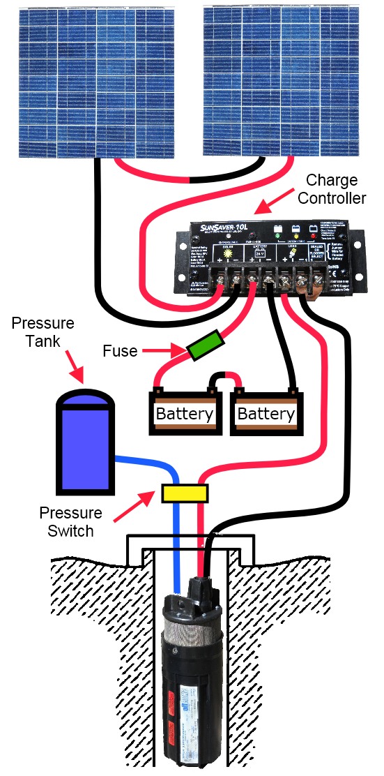
How to use a submersible water pump - 24 volt wiring diagram

Water pump wiring troubleshooting & repair pump wiring diagrams

Single phase control panel wiring diagram | submersible pump ...

Real power engineering - submersible pump control box wiring ...
How to wire submersible motor control box | by "elektricar 1"
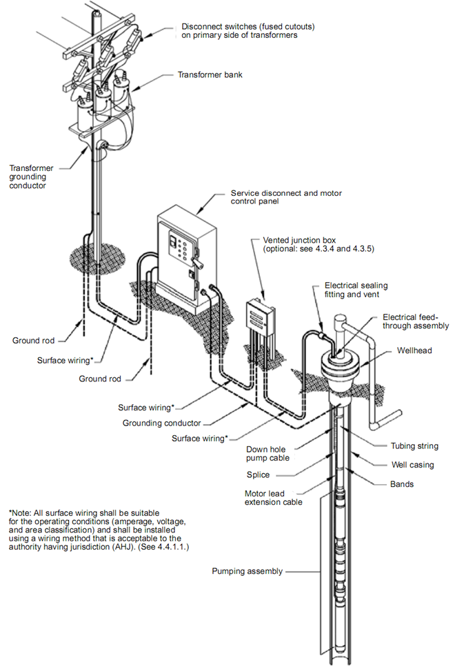
Submersible pump system overview: main surface and downhole ...

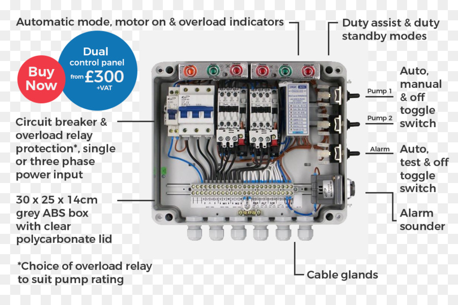
Submersible water pump control panel wiring diagram | electrical technologies

Wiring diagram panel pompa submersible 3 phase

Automatic water level controller circuit diagram for ...

Wiring diagram pompa air
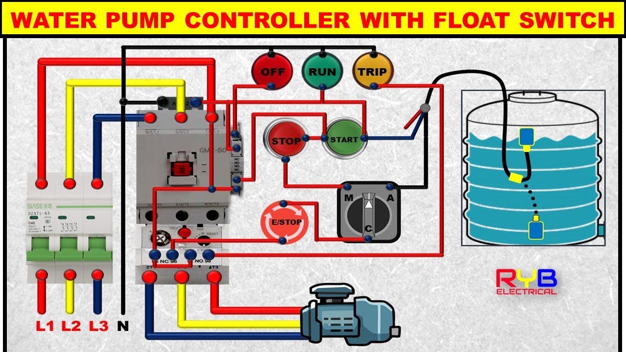
3 phase dol starter control and power wiring diagram! water pump controller with float switch

Grundfos sqflex solar water pump wiring diagram

A guide of auxiliary contact s and it's uses and working ...

Submersible water pump starter wiring connection diagram

Circuit diagram of water pump control system | download ...

Wiring diagram for 220 volt submersible pump, http ...

Submersible pump control wiring diagram - submersible pump box control wiring diagram -control wire

Single phase 3 wire submersible pump wiring diagram

Aim manual - page 54 | single-phase motors and controls ...
Pompa submersible, pompa, diagram pengkabelan gambar png

Electrical education - 3 phase submersible pump wiring ...

Wiring diagram for automatic water pump using floatless level ...

Automatic water level controller wiring diagram for 3 phase
Bagaimana cara menjalankan pompa submersible menggunakan ...

Submersible pump wiring diagram

Detail 44 luxury single phase submersible pump starter wiring ...
How to install and wire a well pump - well pump installation ...

Single phase submersible pump starter wiring diagram gooddy ...
0 Response to "41 submersible pump wiring diagram"
Post a Comment