42 in a state machine diagram, a state is represented by a(n) _______.
A state-machine diagram is usually developed for every class in the problem domain class diagram. ... multiple states. Tags: ... In a state machine diagram, a state is represented by a(n) _____. ...
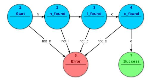
STATE DIAGRAMS ELEMENTS OF DIAGRAMS FINITE STATE MACHINES •STATE MACHINES-INTRODUCTION-MEALY & MOORE MACH.-SYNC. & ASYNC SYSTEMS • A state diagram represents a finite state machine (FSM) and contains • Circles: represent the machine states • Labelled with a binary encoded number or reflecting state.
In a state machine diagram, a state is represented by a(n) ____. oval. Which of the following is NOT a step in the development of a state machine diagram? a. List all the status conditions for an object. b. Identify state exiting transitions. c. Expand the name of each state to identify concurrent activities. d. Sequence the state-transition fragments. c. Expand the name of each state to ...

In a state machine diagram, a state is represented by a(n) _______.
A state machine diagram that shows the Drive Vehicle States and the transitions between them. When the Vehicle is ready to be driven, it is initially in the vehicle off state. The receipt of the ignition on signal from the sequence diagram in Figure 4.6 is an event that triggers a transition to the vehicle on state.
- The state machine is represented as a state transition diagram (or called state diagram) below - One step (i.e., transition) can be taken whenever there is a clock signal State Transition Diagram (or State Diagram) 2 S0 S3 S1 S2 Coover Hall Sweeney Hall Durham Center Parks Library Start • States can be coded as binary combinations of ...
UML State Machine Diagram. The state machine diagram is also called the Statechart or State Transition diagram, which shows the order of states underwent by an object within the system. It captures the software system's behavior. It models the behavior of a class, a subsystem, a package, and a complete system.
In a state machine diagram, a state is represented by a(n) _______..
For example, you can use a state diagram to represent a simplified version of a car's automatic gear transmission. The state machine shown below has four operating states labeled first, second, third, and fourth.Like the gears they represent, these states are exclusive, so only one state is active at a time.
State diagrams can be used to graphically represent finite-state machines (also called finite automata). This was introduced by Claude Shannon and Warren ...
(n) ______ is a naturally occurring association among specific things. relationship ... In a state machine diagram, a state is represented by a(n) ____. Rating: 5 · 1 review
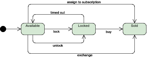
State machine diagram is a behavior diagram which shows discrete behavior of a part of designed system through finite state transitions. State machine diagrams can also be used to express the usage protocol of part of a system. Two kinds of state machines defined in UML 2.4 are behavioral state machine, and; protocol state machine. The following nodes and edges are typically drawn in state ...
State Machine Diagram. In State Machines the vertices represent states of an object in a class and edges represent occurrences of events. The additional notations capture how activities are coordinated. Objects have behaviors and states. The state of an object depends on its current activity or condition.
FINITE STATE MACHINE: PRINCIPLE AND PRACTICE A finite state machine (FSM) is a sequential circuitwith “random”next-statelogic. Unlike the regular sequential circuit discussed in Chapters 8 and 9, the state transitions and event sequence of an FSM do not exhibit a simple pattern. Although the basic block diagram of an FSM is similar to that of a regular sequential circuit, its design ...
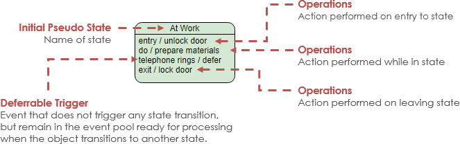
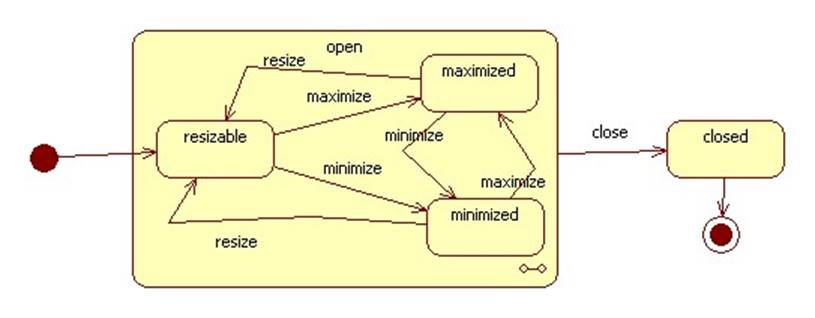
UML 2 Tutorial - State Machine Diagram State Machine Diagrams . A state machine diagram models the behaviour of a single object, specifying the sequence of events that an object goes through during its lifetime in response to events. As an example, the following state machine diagram shows the states that a door goes through during its lifetime. The door can be in one of three states: "Opened ...
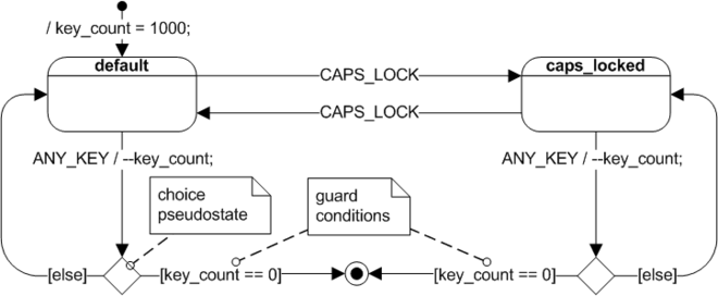
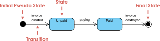
Initial and Final States. The initial state of a state machine diagram, known as an initial pseudo-state, is indicated with a solid circle. A transition from this state will show the first real state The final state of a state machine diagram is shown as concentric circles. An open loop state machine represents an object that may terminate before the system terminates, while a closed loop ...
In a sequence diagram a horizontal dashed line represents what? A return message ... In a state machine diagram, a state is represented by a(n) ____.
In a state machine diagram, a state is represented by a(n) ____. oval. True or False: In an activity diagram, a separate use case may used as part of the workflow. True. A textual model that describes the processing details of a use case is called a(n) _____. use case description. On a sequence diagram when multiple messages are included within a repeating loop a(n) _____ is used to document ...
The easiest way to understand what is a Behavior: It can change your member variable's value. E.g. class MyClass { public Integer i = 0; public void Operation1 () { i++; //This could be an interpretation of of opaque action from an Activity }; public void RunStateMachine () { //You can use state's entry/doActivity/exit behavior. E.g. put "i++ ...
In a state machine diagram, a state is represented by a ______. noun technique. The technique for finding problem domain objects by finding and listing all ... Rating: 5 · 3 reviews
The unified modeling language (uml)- part 7 | the brook song ...
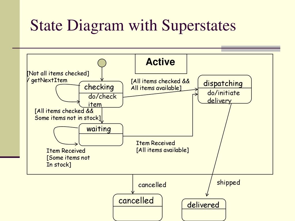
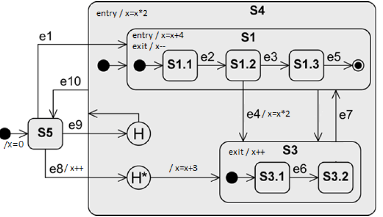
Note that every State Machine has a top State containing all the other elements of the entire State Machine. The graphical rendering of this top state is optional. The states are represented by the State symbols, while the Transitions are represented by arrows connecting the state symbols. The State diagram is concerned with internal object ...
Uml state diagrams. - ppt download
state diagram (state machine diagram or statechart diagram): A state diagram, also called a state machine diagram or statechart diagram, is an illustration of the states an object can attain as well as the transitions between those states in the Unified Modeling Language (UML). In this context, a state defines a stage in the evolution or ...

State diagram - an overview | sciencedirect topics
In State Machines the vertices represent states of an object in a class and edges represent occurrences of events. The additional notations capture how activities are coordinated. Objects have behaviors and states. The state of an object depends on its current activity or condition. A State Machine Diagrams shows the possible states of the object and the transitions that cause a change in state.
Application design patterns: state machines - ni
Here are a few state machines, to give you an idea of the kind of systems we are considering. • A tick-tock machine that generates the sequence 1,0,1,0, . . . is a finite-state machine that ig nores its input. • The controller for a digital watch is a more complicated finite-state machine: it transduces a

State machine diagram - an overview | sciencedirect topics
UML State Machine Diagram Example. This is an example of water phase diagram represented as UML state machine diagram. Water can exist in several states - liquid, vapor, solid, and plasma. Several transitions are possible from one state to another. For example, freezing is phase change from liquid state to ice.
A simple guide to drawing your first state diagram — with ...
State machine diagrams describe the behavior of an object/instance during its whole life span, ... How are states represented in a state machine diagram?
State machine tutorial - uml tutorial
LECTURE #17: Algorithmic State Machines (ASM's) EEL 3701: Digital Logic and Computer Systems ... - Rectangles represent states (state boxes) - The state name is outside the box above the upper left (or right) corner - State bits can also be displayed here ... Complete the timing diagram, given the ASM chart below.
State machine diagram is a uml diagram suitable for | chegg.com
Electronic System Design Finite State Machine Nurul Hazlina 8 Can any sequential system be represented with a state diagram? • Shift register -input value shown on transition arcs -output values shown within state node 100 110 111 011 000 010 101 001 1 1 1 1 0 0 0 0 1
State diagram comprehensive guide with examples | by warren ...
1. A web server can be an actor in a use case diagram. 2. Guarantee is an action that initiates the use case. 3. Use case "Assign seat" includes the use case "Assign window seat". 4. Generalization is represented by an arrow with a hollow triangle head. 5. Every use case might involve only one actor.

The unified modeling language (uml)- part 7 | the brook song ...
A piece of information about a particular object is called a(n) ______. ... A synonym for cardinality (used with UML class diagrams) is ____. Rating: 5 · 7 reviews

Guidelines: statechart diagram
About Press Copyright Contact us Creators Advertise Developers Terms Privacy Policy & Safety How YouTube works Test new features Press Copyright Contact us Creators ...
Desaware inc.- articles: components and tools for microsoft ...
A state diagram is a visual representation of the process that happens in operating a machine within a limited amount of time. This is a type of UML diagram that is frequently used in the engineering field, especially in electronics. The main use of this diagram is to visualize the performance of an object when it undergoes operation.
Uml 2 state machine diagrams
A state diagram, sometimes known as a state machine diagram, is a type of behavioral diagram in the Unified Modeling Language (UML) that shows transitions between various objects. Using our collaborative UML diagram software, build your own state machine diagram with a free Lucidchart account today! 4 minute read.
State machine diagram tutorial
In a transition label in a state machine the syntax is A(B)[C]/D. The D stands ... diagram is used to document the states and transitions of a(n) ______.
Gate cse 2002 | question: 2.5 - gate overflow
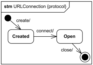
There are a total of two types of state machine diagram in UML: 1. Behavioral State Machine Diagram. It captures the behavior of an entity present in the system. It is used to represent the specific implementation of an element. The behavior of a system can be modelled using behavioral state machine diagram in OOAD. 2. Protocol State Machine ...

Guidelines: statechart diagram
truncated to simply state machine. The current state is a function of past states, and thus the state machine must have memory of its past. A state machine can be represented by a state diagram and/or state transition tables. A counter is a type of state machine. It constantly increases its output value as it sequences
State machines - electronic engineering (mcq) questions & answers
Spring 2010 CSE370 - XIV - Finite State Machines I 3 Example finite state machine diagram 5 states 8 other transitions between states 6 conditioned by input 1 self-transition (on 0 from 001 to 001) 2 independent of input (to/from 111) 1 reset transition (from all states) to state 100 represents 5 transitions (from each state to 100), one a self-arc

The unified modeling language (uml)- part 7 | the brook song ...
- A binary number can represent 2n states, where n is the number of bits. - The number of bits required is determined by the number of states. Ex. 4 states requires 2 bits (22 = 4 possible states) Ex. 19 states requires 5 bits (25 = 32 possible states) - One flip-flop is required per state bit. Steps to Design Sequential Circuits: 1) Draw a ...

The unified modeling language (uml)- part 7 | the brook song ...
An FSM whose output reflects both current state and current inputs is termed a Mealy machine, and requires slightly different set of conventions for its state transition diagram. As Mealy machine outputs are not functions only of states, the edges of a Mealy machine diagram are often annotated with output values as well as input criteria, as ...
Finite state machines
UML state machine diagram - parallel processes. i am trying to develop an UML state machine diagram for the following problem: a vending machine has 3 buttons: R for 'return money, A & B for drink selections. when the vending machine receives amount x of money the user can choose between the drinks. pressing R returns the money without serving ...
Solved figure 1 finite state machine a current state is ...
State Diagram Definition. A state diagram - also known as state chart, state machine diagram or state transition diagram - visualises a sequence of states that an object can assume in its lifecycle. It is used to describe the behavior of a system, subsystem, component, or class. The use of system interfaces can also be specified by state diagrams.
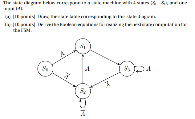
Solved the state diagram below correspond to a state machine ...

Uml state machines used to model the dynamic behaviour of a ...
State machine diagram tutorial
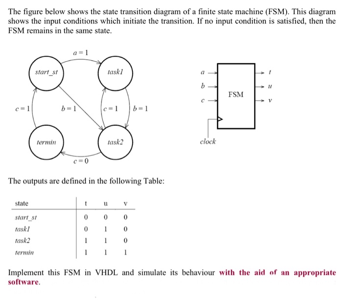
Solved the figure below shows the state transition diagram ...
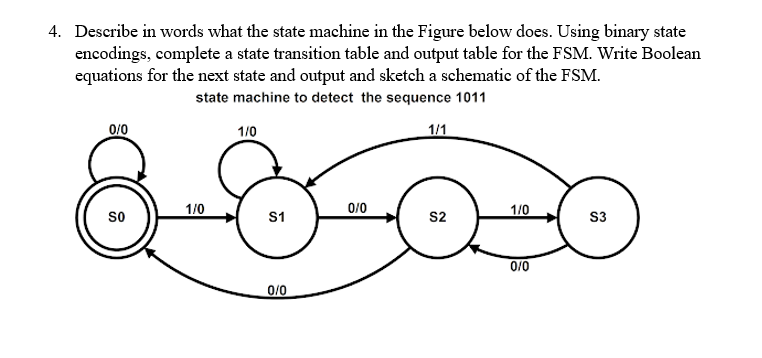
Solved 1. describe in words what the state machine in the ...
Part 2 – state machine diagrams

State machine diagram - uml 2 tutorial | sparx systems
State machine tutorial - uml tutorial
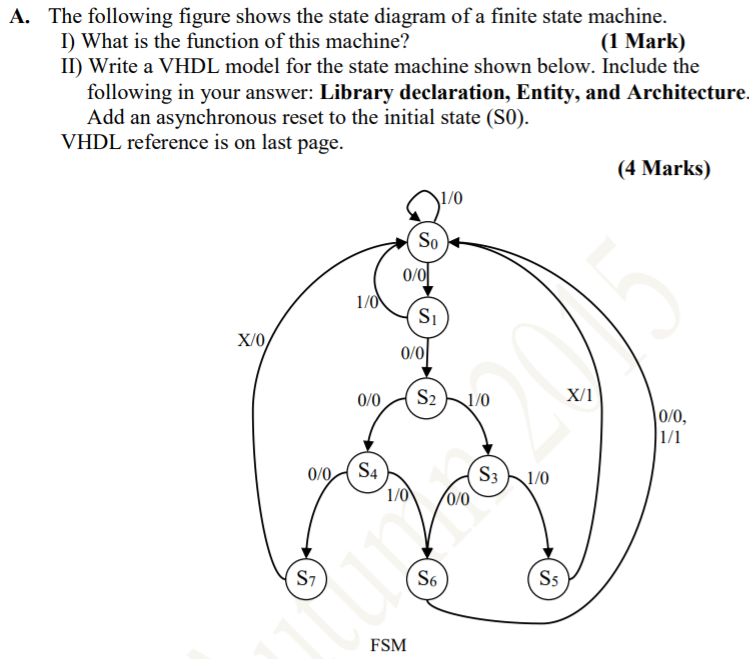
Solved a. the following figure shows the state diagram of a ...
State diagram comprehensive guide with examples | by warren ...

Guidelines: statechart diagram
Unit 5 what is state? state machine block diagram state diagrams
State machine diagram tutorial | lucidchart
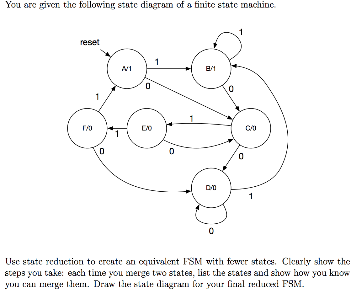
Solved you are given the following state diagram of a finite ...

The unified modeling language (uml)- part 7 | the brook song ...

The unified modeling language (uml)- part 7 | the brook song ...
Uml state machine diagrams - graphical notation reference

The unified modeling language (uml)- part 7 | the brook song ...
State machine tutorial - uml tutorial

State machine diagram - an overview | sciencedirect topics
0 Response to "42 in a state machine diagram, a state is represented by a(n) _______."
Post a Comment