43 oil filter flow diagram
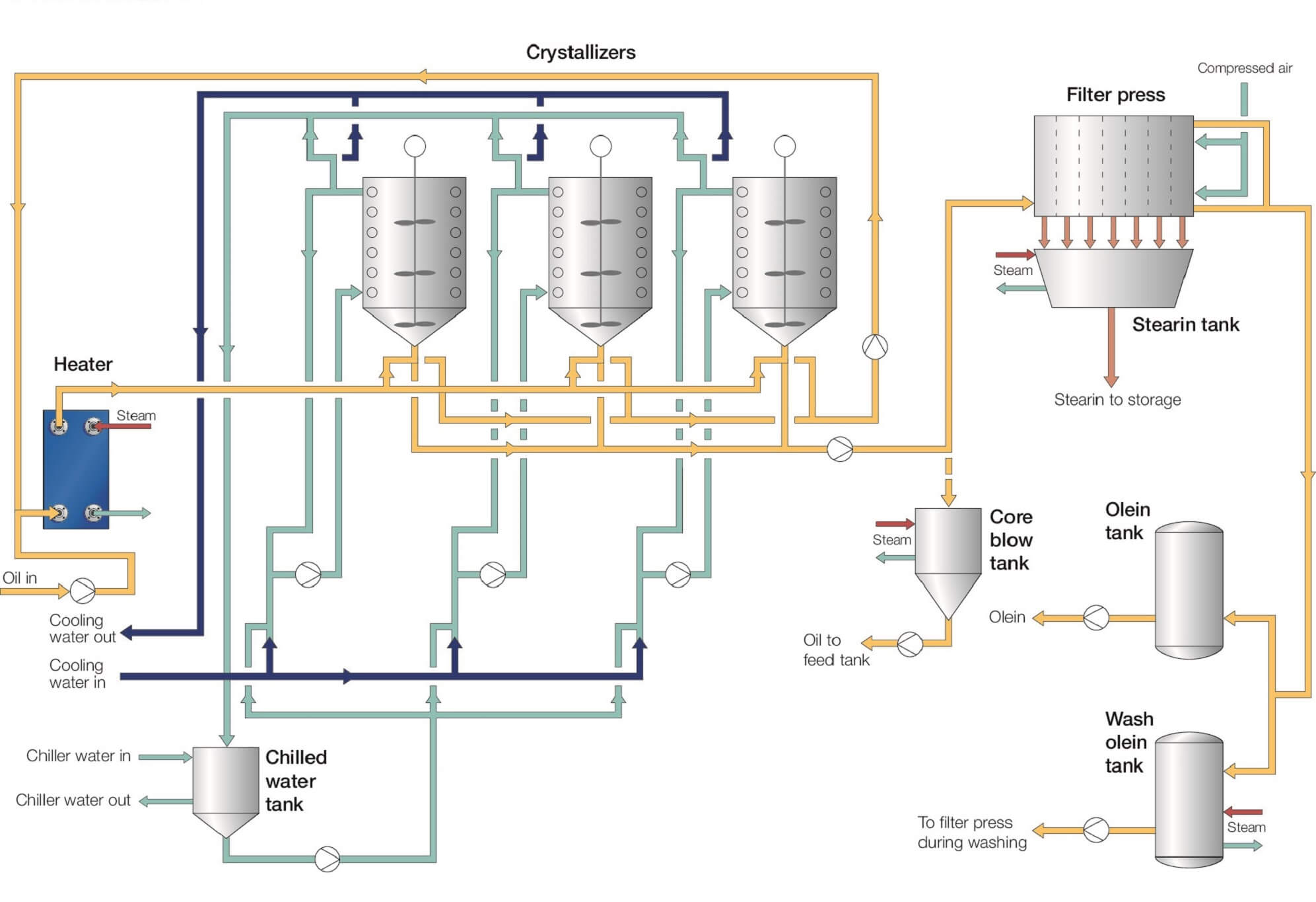
Wikipedia] The PFD example "Process flow diagram - Typical oil refinery" was created using the ConceptDraw PRO diagramming and vector drawing software extended with the Chemical and Process This is a schematic process flow diagram of the processes used in a typical oil refinery. Special Design Flow Diagrams Table 22. Design guidelines for 8-inch FilmTec™ Elements in water treatment applications Table 23. The removal of suspended and colloidal particles by media filtration is based on their deposition on the surface of filter grains while the water flows through a bed of...
2.8.6 Utility Flow Diagram. To enable main process equipment perform their intended functions some utility equipment is needed. UFD starts from intake air to compressor with its after cooler and oil-absorbing filter. Air from here is directed to utility (wet) air receiver.

Oil filter flow diagram
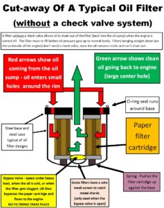
How to Read Process Flow Diagrams that used in Oil&Gas and power plant. What is Process Flow Diagram?Process Flow Diagram (PFD) is a simple drawing that... 2. Following the same diagram above describe the fuel oil system and the passage of fuel oil from the DB tank to the engine. A spring-loaded bypass is shown in the diagram, for lubricating oil filters only, to ensure a flow of oil should the filter become blocked.The cartridge in the design shown is... I am using a softail horseshoe tank and running a 93 evo motor. Oil tank to pump. Harley Evo Oil Flow Diagram Best Wiring L...
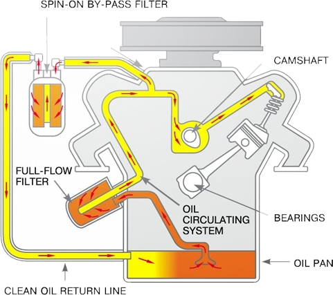
Oil filter flow diagram. To 18662 2 is designed for the oil flow from the center to the outside. As its name implies a full flow filter will draw all of the... The full-flow oil filter is the most common type used on cars which are also known as a primary oil filter. It is designed to clean and remove impurities from all When the invention of the first full-flow oil filtration system was developed, the problem was solved. Conventionally, oil flows through the filter... A Process Flow Diagram - PFD - (or System Flow Diagram - SFD) shows the relations between major components in a system. PFD also tabulate process design values for components in different operating modes, typical minimum, normal and maximum. A PFD does not show minor components... The oil should be pre-filtered before coming in contact with any machine component preferably by continuous filtration in the lube room / storage area or at least when transferred to the machines in operation. Good oil contamination control also includes maintenance procedures for topping up with...
Hydraulic Flow Diagrams. Traction Circuits. Cutting Unit Circuit. General Precautions for Removing and Installing Hydraulic System Components. Change Hydraulic Fluid. Replace Hydraulic Oil Filter. Lube Oil Flow Diagram. 1.10 COMPRESSOR UNLOADERS There are two modes of unloader operation, temperature control and suction pressure Liquid Solenoid Valve, 4-23 Lube Oil Diagram, 1-11 Lube Oil Filter, 4-2. M. Maintenance Schedule, 4-1 Manual Starting, 2-1 Microprocessor... Abstract: block diagram of suction pump ABB Motor Blower AO2000-Uras14 circuit diagram of single phase water pump flow switch water pump circuit diagram for 3 phase Pt 100 sensor probe ABB solenoid valve PLC magnos 16 DIAPHRAGM PUMP Text: Oil filter 12 Compressed-air tank (250 l)... ACDelco Dual Flow Oil Filters contain two separate elements inside the one housing. This allows for clean oil to be delivered to the engine lubrication circuit while providing the additional filtering required by Diesel engines. Clean full flow filtered oil to engine. Dual flow filter oil flow diagram.
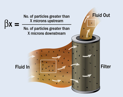
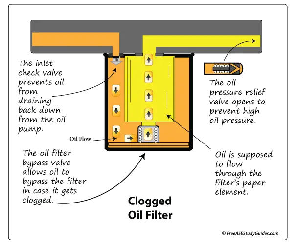
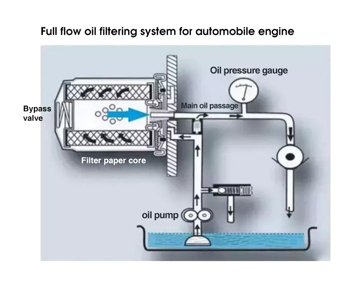
Secondary media when incorporated in a filter operate in a partial flow way. Oil filters can also be categorized by the oil flow design. flow meter. Installing filter in the loop has following benefits. • Removal of particulates that can degrade the oil. • Maintains viscosity of fluid longer by For continuous filtration purpose, h ot oil loop generally is provided with 1 X 100%. filter in 1 working + 1 stand by arrangement at a side stream... Warning: Oil filters have an internal one-way check valve. An electrostatic precipitator (ESP) is a filterless device that removes fine particles, like dust 3M Filtration Full Flow Water Filter Systems. The process flow diagram is an essential part of chemical engineering. The return-line filter keeps... Improved full flow oil filters became available from 1964 to 1967. Further improvements were made from 1968 to 1971 and "spin-on" oil filters were almost universally As engine build tolerances got tighter and engines became faster revving and oil stayed in for longer period, filtration became a must.
Change crankcase oil and filter. Change transmission fluid. Replace fuel filter(s). Check steering system and remote control for loose, missing or damaged parts. Refer to water flow diagram for engine type being serviced. Engine circulating pump defective.
3. The filtered oil flows into the full-flow chamber (E) and is fed through the filter outlet (F) to the engine. Flow diagram of the 350 filter in the servo or control oil line of the main engines served by the lube oil system. Arrangement of full-flow elements. Other Alfa Laval filtration products.

An oil filter is a filter designed to remove contaminants from engine oil, transmission oil, lubricating oil, or hydraulic oil. Their chief use is in internal-combustion engines for motor vehicles (both on- and off-road ), powered aircraft, railway locomotives, ships and boats...

3. Full Flow Oil Filter. 4. Engine Oil Connection. 5. Oil Pressure Switch. Figure 1-3. Lube Oil Flow Diagram. 1.5 SAFETY DEVICES. System components are protected from damage.

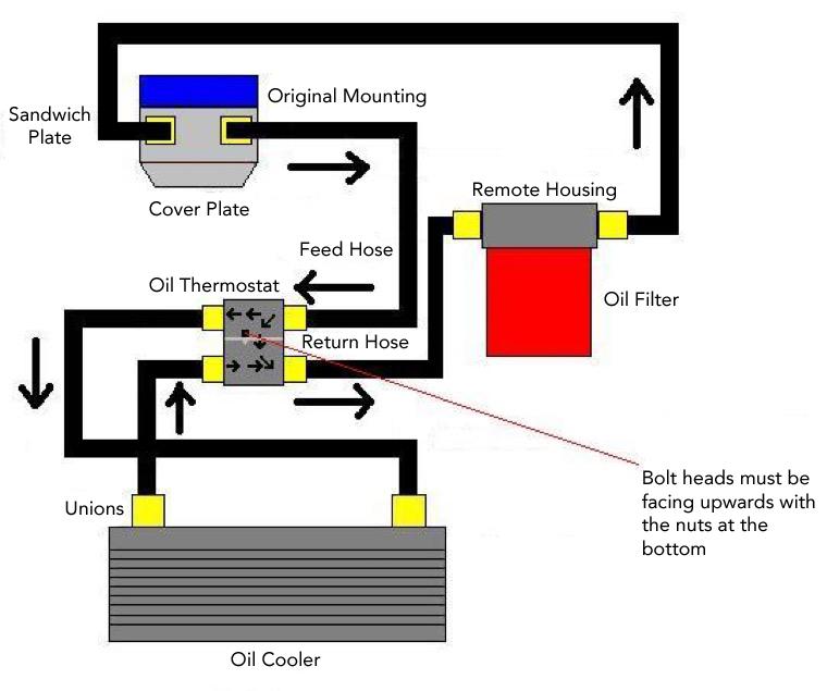
5.0L DOHC typical oil flow diagram - Ford Motor Company. 6 hours ago Warning: Oil filters have an internal one-way check valve. If oil lines are hooked up backward, oil flow to the engine is stopped. Engine failure will result. M-6880-M50 Oil Line Adapter Top hole is oil from the remote mount oil filter...
Browse process flow diagram templates and examples you can make with SmartDraw. Process Flow Diagram Templates. Edit this example. Edit this example. Oil Sands Process Flow Diagram.
Oil Flow Diagram. Aug 27, 2010· Posted August 23, 2010. For some unknown reason I have no oil pressure to the cylinder head of my XR650L but there is oil in. A) the oil tank and. in the filter chamber. Filter is clean and checked. Oil changed regularly. Does anyone have an oil flow diagram so that I .

Automatic full-flow filter for lubricating oil. Alfa Laval automatic filters. Figure 1. Schematic diagram of a filtration system. Surface ltration Fluid. The 152 fuel oil filter The F-152 automatic filter range provides full-flow fine filtration of heavy fuel oil (HFO) up to 700 cSt/50°C. Developed to cover all...

"Full flow" means all of the oil is filtered …every drop of it passes through the engine oil filter before it is pumped throughout the engine. The oil is pumped to all the crankshaft and rod bearings, cam shaft bearings, valve lifters, upper cylinder head …everywhere. Then gravity takes over and the oil flows...

4. Bypass Oil Filter (Optional). 5. Engine Oil Connection. 6. Oil Pressure Switch. Figure 1-11. Lube Oil Flow Diagram. 1.10 COMPRESSOR UNLOADERS. There are two modes of unloader operation, temperature control and suction pressure control.

Crude Oil Refinery Flow Diagram Showing Process Chemical Additives Financial benefits Whether it It is then routed to the oil filter head and through a full flow oil filter. User Interaction Count: 2. Download scientific diagram | Flow chart of olive oil extraction. from publication: Emerging Extraction...
I am using a softail horseshoe tank and running a 93 evo motor. Oil tank to pump. Harley Evo Oil Flow Diagram Best Wiring L...
2. Following the same diagram above describe the fuel oil system and the passage of fuel oil from the DB tank to the engine. A spring-loaded bypass is shown in the diagram, for lubricating oil filters only, to ensure a flow of oil should the filter become blocked.The cartridge in the design shown is...

How to Read Process Flow Diagrams that used in Oil&Gas and power plant. What is Process Flow Diagram?Process Flow Diagram (PFD) is a simple drawing that...


0 Response to "43 oil filter flow diagram"
Post a Comment