43 vdo tach wiring diagram
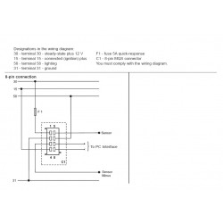
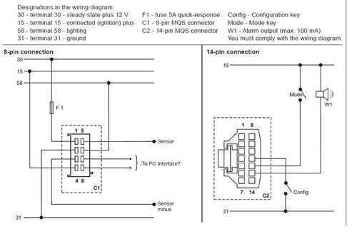
Tachometer, without Display 13 GB 14 Connector set, 8-pin A2C59510850 30 - terminal 30 - steady-state plus 12 V 15 - terminal 15 - connected (ignition) plus 58 - terminal 58 - lighting 31 - terminal 31 - ground Designations in the wiring diagram: 8-pin connection F1 - fuse 5A quick-response C1 - 8-pin MQS connector You must comply with the ... VDO cockpit vision VDO cockpit international Contents Page 2.1 General informations 2 - 2 2.2 Technical data 2 - 4 2.3 Speed sensor 2 - 8 2.4 Wiring diagrams 2 - 9 2.5 Setting 2 - 11 2.6 Operation 2 - 16 2.7 Speed display 2 - 17 2.8 Testing instructions 2 - 18 2.9 Instruments survey 2 - 21 Installation instructions 999-165-001: VDO cockpit ...
Tach Wiring Diagram - dixco tach wiring diagram, harley tach wiring diagram, pro tach wiring diagram, Every electric arrangement is composed of various distinct pieces. Each component ought to be placed and connected with other parts in particular manner. Otherwise, the arrangement will not work as it ought to be.
Vdo tach wiring diagram
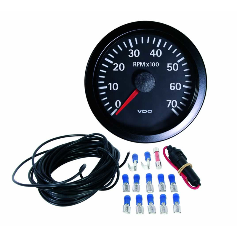
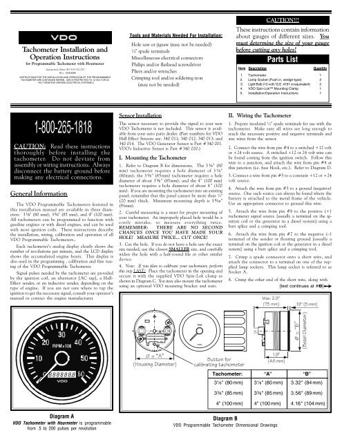
Diagram A VDO Tachometer with Hourmeter is programmable from .5 to 200 pulses per revolution VDO VDO Item Description Quantity 1. Tachometer 1 2. Lamp Socket (Push in, wedge-type) 2 3. Light Bulb (12-volt / G.E. #161 or equivalent) 2 4. VDO Spin-Lok™ Mounting Clamp 1 5. Installation/Operation Instructions 1 Parts List These instructions ... according to the electrical wiring diagram. † If operating the instrument on power supply units, note that the power supply unit must be stabilized and it must comply with the following standard: DIN EN 61000, Parts 6-1 to 6-4. ... Procedures for installing VDO Viewline instruments. 03/11 INSTALLATION INSTRUCTIONS: Viewline 52 mm Vdo Tachograph Wiring Diagram. By Admin | November 4, 2017. 0 Comment. Digital tachograph monitoring wiki knowledge base teltonika gps vdo viewline tachometer 3 000 rpm black 85mm installation and operations instructions with display manual manualzz engine oil pressure 10bar white 52mm ruptela solution configuration emulator simulator 4 tacho ...
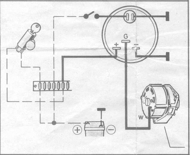
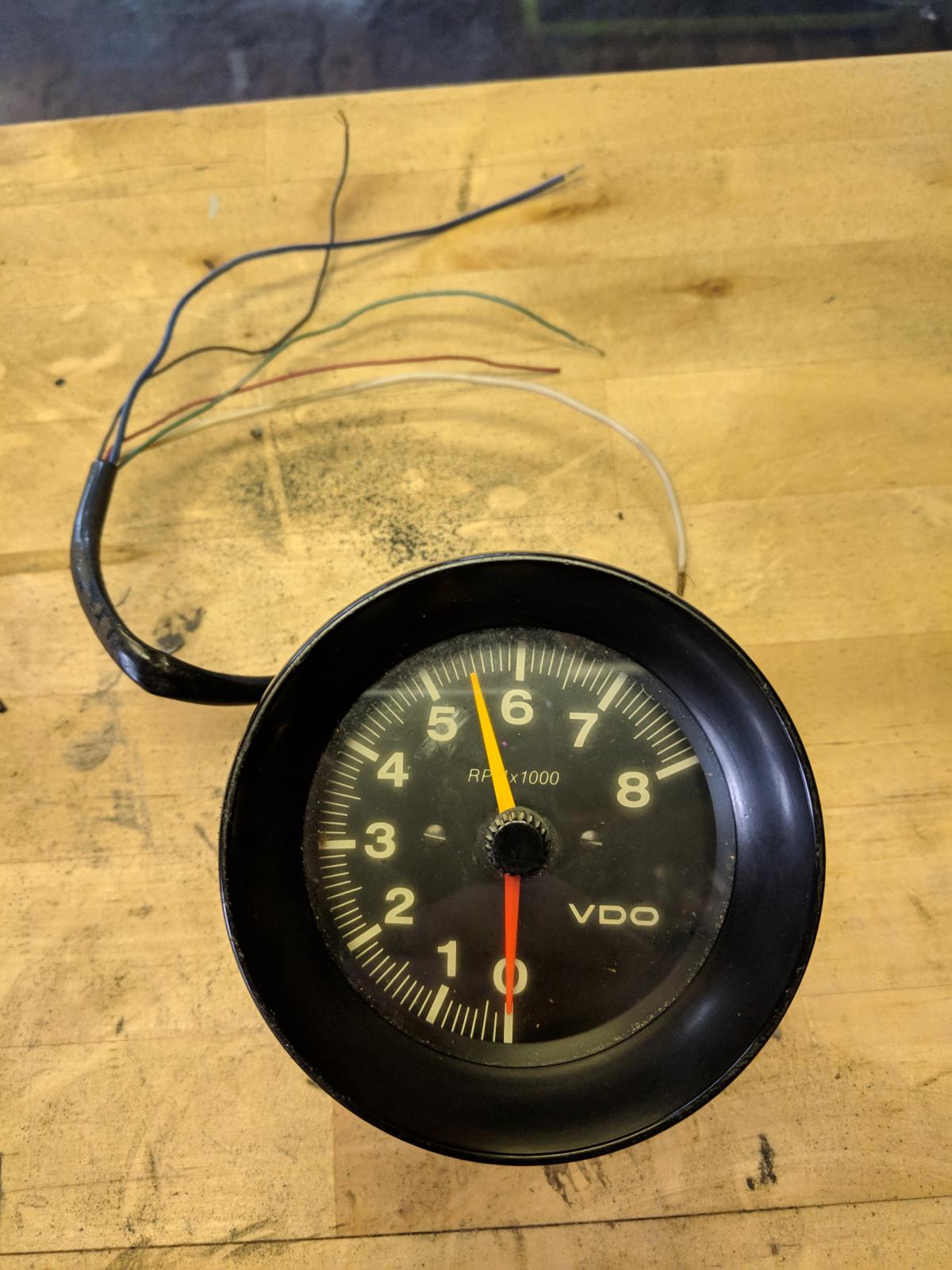
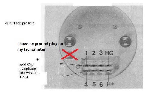
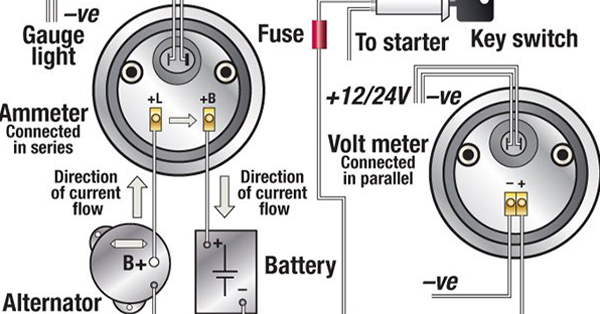
Vdo tach wiring diagram. For 'Garcons' analog tachometer like the above photo tachometer, wiring connections are as below: Yellow wire is connected to ignition switch ON position, to connect to positive ( + ). Green wire to negative ( - ) or body or ground wire. Black wire for signal, connected to negative of coil, to allow tacho to 'sense' engine speed. Vdo Gauges Wiring Diagram. The VDO Programmable Speedometer featured in this installation Refer to diagram B below for the sender wiring for a hall- wiring more than one gauge. VDO cockpit vision VDO cockpit international. Published by: . steel, zinc-plated and chromatized (ammeter, turbocharger gauge) . VDO Cylinder Head Temperature Gauge Handlebar/Fairing Mount - 2009. VDO Resitive Gauge wiring Instructions - 2009. Veratron Flex Gauge 52mm NMEA2000 12/24v. ViewLine 52mm Wiring Diagram (2014) ViewLine Standard Resistive Gauges 52mm Installation Sheet (2014) Viewline Temperature Gauges 12/24 Volt (2011) Viewline Temperature Gauges 52mm (2008) Diagram E Proper wiring of the VDO Programmable Tachometer with typical ignition systems ˘ˇˆ ˙˘ ˝ˇ! "˙ Diagram F Fine adjustment of the VDO Tachometer when used with an alternator Compare the VDO Tachometer reading with that of a reference tachometer. Adjust the potentiometer on the back of the tach. When the VDO Tachometer reading.
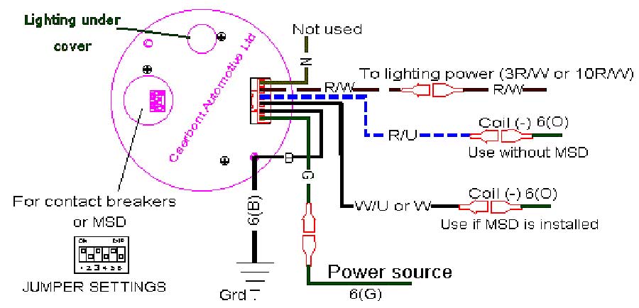
VDO Tach Wiring. Post by chitwnvw » Sun Jul 01, 2007 12:49 am I am trying to get my VDO tach going. The backside has a positive, negative, ground and light spade. ... According to the wiring diagram the G is suppost to hook up to the negitive side of the coil. Vdo Tachometer Wiring Diagram Cocosweetpea. Vdo Tachometer 0 515 012 037 Manualzz. Tachometer Installation And Operations Instructions. Diagram Vdo Wiring Gauge Tach Full Version Hd Quality Forexdiagrams Sitrend It. Vdo Viewline Tachometer 6 000 Rpm Black 85mm. 0 515 012 020 Programmable Tachs Without Hourmeters Rev 02 01 P65. plan to calibrate your tachometer, skip Step 3 and return after calibration is completed. 3. Place the tachometer in the opening and secure with the VDO Spin-Lok clamp provided (see diagram B). You may also mount the tachometer with a VDO mounting bracket and nuts (purchased separately). Diagram B Dash Panel 3/4" [20mm] maximum thickness Dash Panel • VDO does not recommend mounting your Xtreme 3. Wiring the Tachometer • Turn off the ignition and disconnect the negative terminal from the battery post if you haven™t already done so. • Wire the tachometer to the vehicle as shown in either Diagram C * or Diagram D *. * Refer to your vehicle™s owner/service manual or the
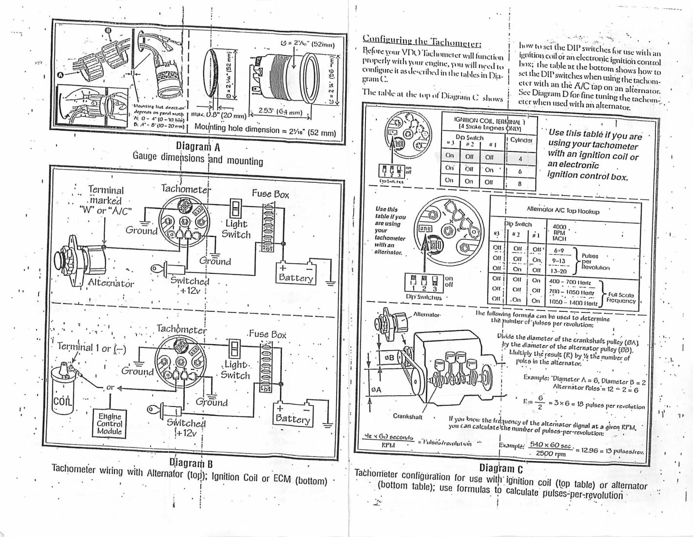
description in Diagram C. d) the location of the signal source (alternator, coil or other ignition signal source). 2. Connect the wiring to the appropriate tachometer terminals as shown in Diagram C. Configuring the T achometer: Before your VDO Tachometer will func-tion properly with your engine, you will need to configure it as shown in Diagram D. Tachometer Signal Wire from Electronic Ignition Box Electronic Ignition Control Box Pin #3 Pin #3 Pin #3 Pin #4 Ignition Battery Butt Splice Fuse Block Light Switch Back of Speedometer Pin #2 ... VDO Installation Guide.ai Author: marcusj Created Date: 2/19/2015 1:29:16 PM ... Vdo Tachometer Wiring Diagram - wiring diagram is a simplified suitable pictorial representation of an electrical circuit. It shows the components of the circuit as simplified shapes, and the capability and signal connections amongst the devices. A wiring diagram usually gives guidance virtually the relative slope and concord of devices and ... dealer or VDO Instruments at 1-800-265-1818. Installing the tachometer is a three-step process. First, you must program the tachometer to match the number of cylin-ders your engine has and the type of ignition your are using. Next, you must determine where to mount the tachometer and which optional mounting brackets, if any, you need.
VDO cockpit vision VDO cockpit international . (diameter 52 mm: tachometer, clock, operating hours counter, pyrometer; diameter . Wiring diagrams. 2 - 9. See page 2 - Setting up the Tachometer. 3. Mount the gauge and secure with the VDO Spin-Lok™. Clamp. (See page 4 for from assembly or wiring diagram. Tachometer, without Display.
Use a wrench to tighten the nuts until the tachometer can not longer be rotated by hand. DO NOT OVERTIGHTEN. See Diagram C. Wiring the Tachometer: iring your new VDO Tachometer is a simple and straightforward procedure, as shown in Diagram D. al, or the spot where the negative battery fuse box); and
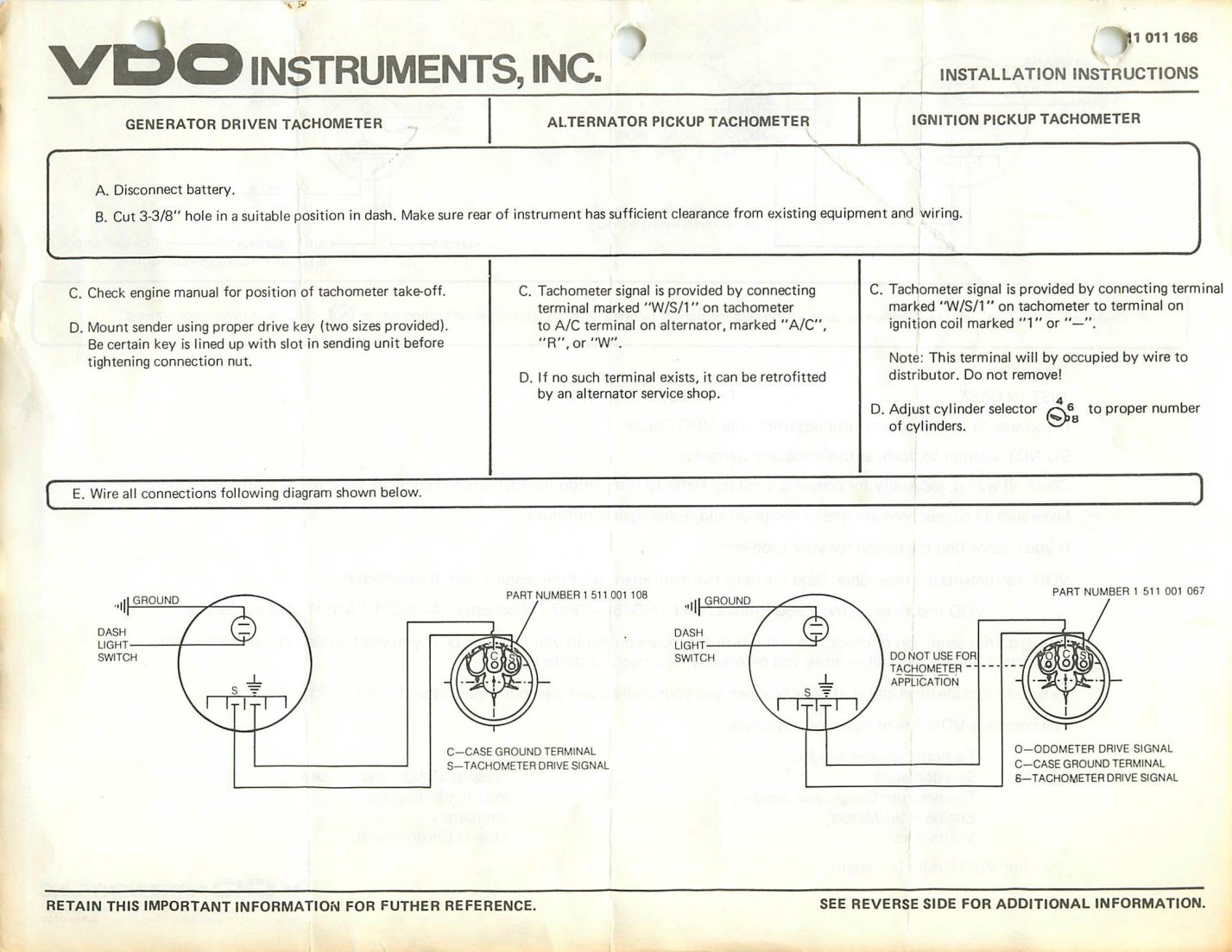
Diagram E Proper wiring of the VDO Programmable Tachometer with typical ignition systems ˘ˇˆ ˙˘ ˝ˇ ! "˙ Diagram F Fine adjustment of the VDO Tachometer when used with an alternator Compare the VDO Tachometer reading with that of a reference tachometer. Adjust the potentiometer on the back of the tach. When the VDO Tachometer reading
A Vdo Marine Tachometer Wiring Diagram can be really a compacted conventional pictorial representation of a electric circuit. It shows that the components of the circuit because simplified shapes, and also the power and signal connections in between the apparatus. vdo tach wiring instructions - wiring library •, size.

Vdo Marine Tachometer Wiring Diagram - Data Wiring Diagram Schematic - Tachometer Wiring Diagram. You are able to always depend on Wiring Diagram as an crucial reference that will help you preserve money and time. With all the aid of the book, you are able to easily do your own personal wiring projects.
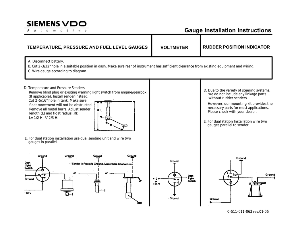
Diagram A Tachometer with Hourmeter is programmable from .5 to 200 pulses per revolution VDO Tachometer Installation and Operation Instructions for Programmable Tachometer with Hourmeter CAUTION; Read these instructions thoroughly before installing the tachometer. Do not deviate from assembly or wiring instructions. Always disconnect the ...

Diagram C Proper mounting of the Eliminator RF/EMF Filter on the back of the Tachometer Tachometer Installation and Operation Instructions Addendum for Comp Eliminator II Tachometer Siemens VDO ® Allentown, Pennsylvania USA THE INSTRUCTIONS FOR OPERATION AND ELECTRICAL WIRING FOR THIS TACHOMETER FOLLOWS.
-515-010-554. If you have additional questions please contact VDO: Aftermarket Technical Support & Troubleshooting. autotechsupport@vdo.com. Repair & Service for Aftermarket Gauges and Accessories. Connie Heflin. Phone: 540-678-2034. Fax: 540-662-2515. cheflin@vdo.com.

Boat Gauge Wiring Diagram For Tachometer - thanks for visiting my site, this post will discuss concerning Boat Gauge Wiring Diagram For Tachometer. We have gathered numerous pictures, hopefully this picture works for you, and also assist you in locating the response you are looking for. Description : Vdo Gauges Wiring
See page 2 - Setting up the Tachometer. 3. Mount the gauge and secure with the VDO Spin-Lok™ ... from assembly or wiring diagram. Always disconnect battery ground before making any electrical connections. IMPORTANT: Mounting dimensions vary for different gauges. Please ... On any VDO part or VDO product found to be defective after
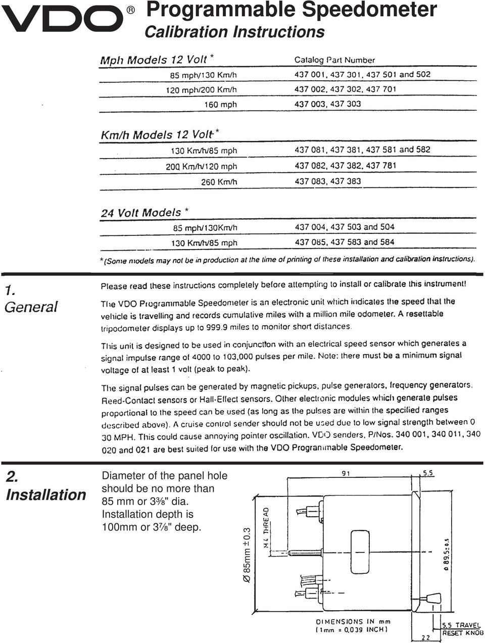
dealer or VDO Instruments at 1-800-265-1818. General Information: These kits come with VDO™s Spin-Lok Mounting Clamps for easy installation. Optional VDO mounting brackets are available from your VDO dealer, should you require them. Note that the pro-grammable speedometer included in this kit has a special set of in-
Vdo Tachograph Wiring Diagram. By Admin | November 4, 2017. 0 Comment. Digital tachograph monitoring wiki knowledge base teltonika gps vdo viewline tachometer 3 000 rpm black 85mm installation and operations instructions with display manual manualzz engine oil pressure 10bar white 52mm ruptela solution configuration emulator simulator 4 tacho ...

according to the electrical wiring diagram. † If operating the instrument on power supply units, note that the power supply unit must be stabilized and it must comply with the following standard: DIN EN 61000, Parts 6-1 to 6-4. ... Procedures for installing VDO Viewline instruments. 03/11 INSTALLATION INSTRUCTIONS: Viewline 52 mm

Diagram A VDO Tachometer with Hourmeter is programmable from .5 to 200 pulses per revolution VDO VDO Item Description Quantity 1. Tachometer 1 2. Lamp Socket (Push in, wedge-type) 2 3. Light Bulb (12-volt / G.E. #161 or equivalent) 2 4. VDO Spin-Lok™ Mounting Clamp 1 5. Installation/Operation Instructions 1 Parts List These instructions ...


0 Response to "43 vdo tach wiring diagram"
Post a Comment