44 emergency ballast wiring diagram
Fluorescent Ballast Wiring Diagram - 8 foot fluorescent ballast wiring diagram, advance fluorescent ballast wiring diagram, compact fluorescent ballast wiring diagram, Every electric arrangement is composed of various diverse pieces. Each component ought to be placed and connected with different parts in particular manner. Otherwise, the structure won't function as it ought to be. IOTA's LED emergency drivers and emergency ballasts allow LED and fluorescent fixtures to serve as emergency lighting sources. Explore our innovative product line with solutions for field installation, self-testing, CA Title 20, LED retrofit and more.
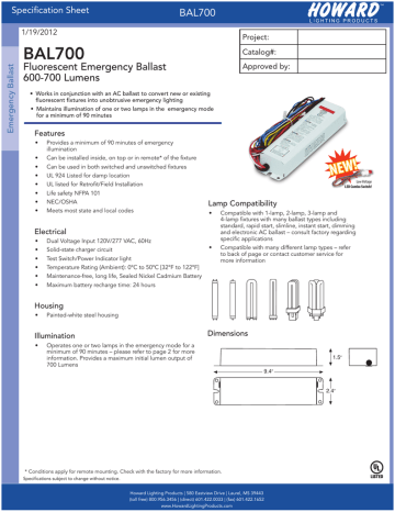
2. Select the appropriate wiring diagram to connect the emergency ballast to the AC ballast and lamp. Make sure all connections are in accordance with the National Electrical Code and any local regulations. manufacturer. 3. Install the test switch through the ballast channel cover of a troffer or through the side of a strip fixture. Drill a
Emergency ballast wiring diagram
Iota Emergency Ballast Wiring Diagram from diagramweb.net. Print the electrical wiring diagram off in addition to use highlighters in order to trace the signal. When you employ your finger or even the actual circuit together with your eyes, it's easy to mistrace the circuit. One trick that I 2 to print exactly the same wiring picture off twice. INSTRUCTIONS FOR PROPER POLARITY WIRING. ... TWO LAMP ELECTRONIC BALLAST. EMERGENCY. BALLAST. 2LEB. RED OR. RED/BLK(+). ➂. SELECT PROPER VOLTAGE LEAD. Emergency ballast wiring diagram. Literally a circuit is the path that enables electrical energy to circulation. A wiring diagram is a streamlined standard photographic representation of an electrical circuit. It shows the components of the circuit as simplified forms and the power and signal links in between the devices. A very first consider a circuit diagram could be confusing yet if you ...
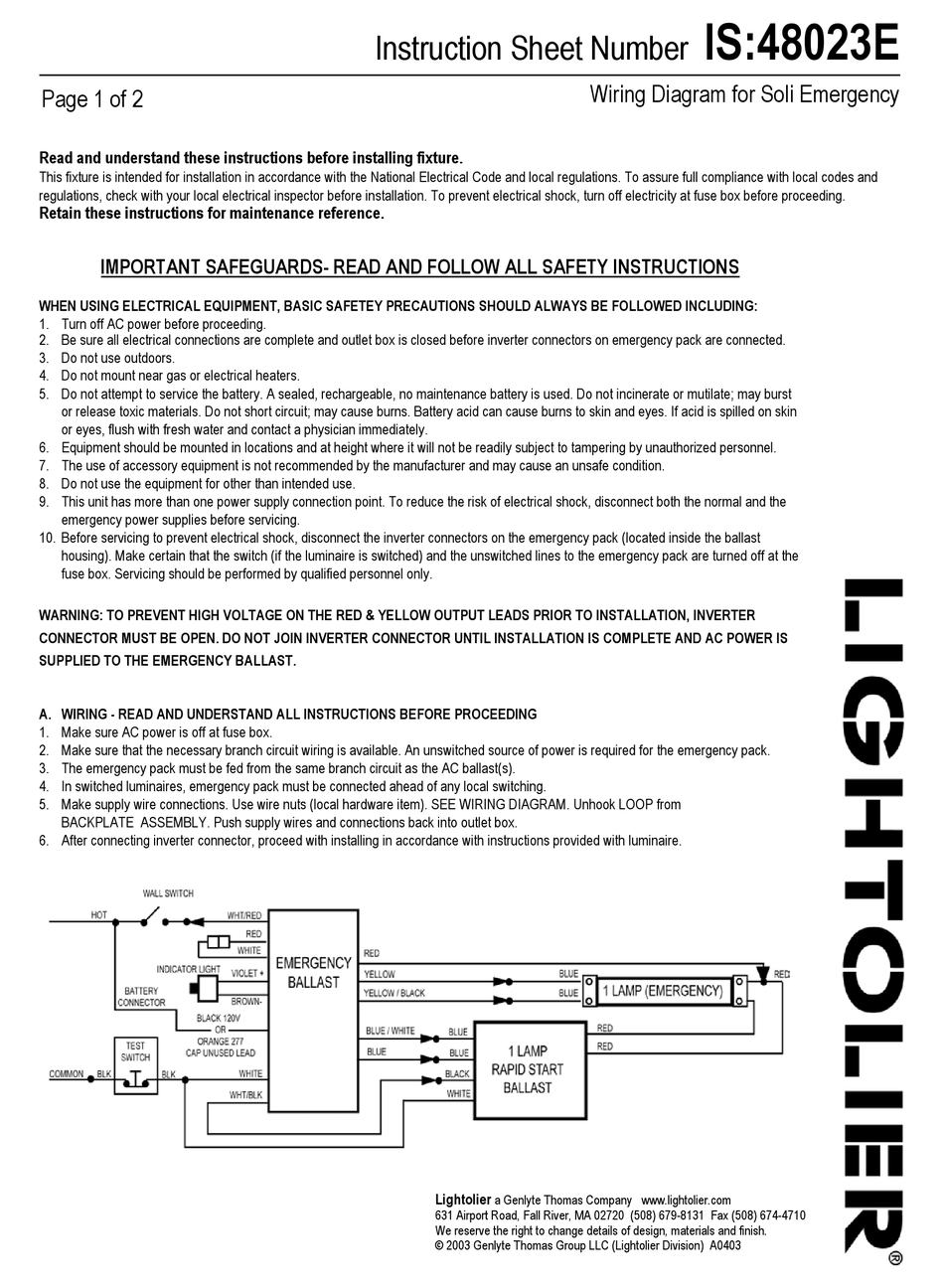
Emergency ballast wiring diagram. Free delivery on orders over £150. T8/T5 Ballast Wiring Diagram available for reference online at EML Direct. All diagrams are available in PDF format for viewing on almost any device. wiring diagrams for retrofit installation, are supplied with each ballast. To prevent high voltage from being present on the DEB-1W output leads (red and yellow), do not join the battery connector until installation is complete and AC power is supplied to the DEB-1W. The DEB-1W emergency ballast is approved for installation inside, on top of, or WIRING DIAGRAM for EMERGENCY OPERATION at 120V-277V Emergency Ballast and AC Ballast must be fed from the same circuit Easy Installation & Product Help Tech Help Line Call our experts 888 RAB-1000 ©2012 RAB LIGHTING Inc. Northvale, New Jersey 07647 USA rabweb.com Visit our website for product info email Answered promptly sales@rabweb.com PANEL2X4 EM IN-0914 Iota Emergency Ballast Wiring Diagram Collection. Collection of iota emergency ballast wiring diagram. A wiring diagram is a simplified traditional photographic representation of an electric circuit. It shows the parts of the circuit as simplified forms, and the power and also signal links between the gadgets. A wiring diagram typically offers details concerning the family member…
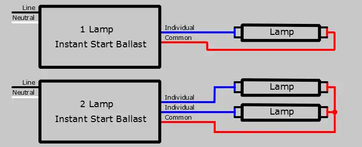
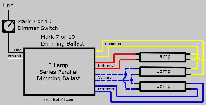
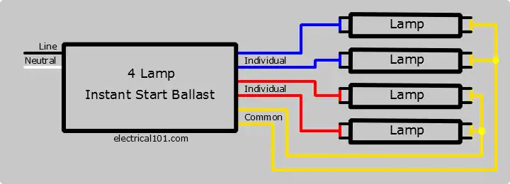
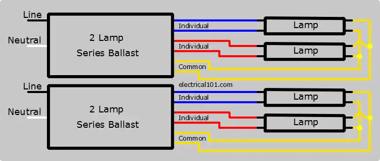
CONSULT THE FACTORY FOR OTHER WIRING DIAGRAMS. EMERGENCY BALLAST AND AC BALLAST MUST BE FED FROM THE SAME BRANCH CIRCUIT. 2.A) FLEX Conduit Wiring Diagram:. 30 Trends Ideas Tridonic Ballast Wiring Diagram Stephan Fuchs. Tridonic beş a elektronik pca xitec ll product manual ballast t5 wiring diagram pc pro lp 14 80 w t8 em powerled basic 4 converterled nicd nimh 50 v power packs axiom computerised series 3 4x18 emergency lighting units inverter bodine b50 sl 250 kit led driver fluoescent advice required tec 18 58 st mh lifepo4 dd sc 28 55 tc top ... Instant start ballasts can only be wired in parallel according to the diagram on the ballast. Changing the wiring on a fluorescent light fixture from rapid start to instant start, involves changing the wiring from series to parallel. 1 Lamp Rapid Start Ballast Diagram. 1 Lamp Instant Start Ballast Diagram. Wired in series. Wired in parallel. Grounding a Ballast. Grounding a ballast is very ... Mount the ISL-28 in the ballast channel at least 1/ 2″ away from the A.C. ballast(s). When battery packs are remote mounted, consult Customer Service for the maximum allowable distance between the battery pack and the lamp. 3.WIRING Refer to the wiring diagrams on the back page for the appropriate wiring of lamp(s) and ballast. Install in accor-
fbp 1 40x fluorescent emergency ballast wiring diagram - What is a Wiring Diagram? A wiring diagram is an easy visual representation from the physical connections and physical layout of the electrical system or circuit. CAUTION: The emergency ballast and AC ballast must be fed from the same branch circuit, reference wiring diagram for applicable lamp and ballast configuration.5 pages C. When the EMERGENCY BALLAST is used with a switched fixture, A.C. Input to the EMERGENCY BALLAST must be connected ahead of the fixture switch. Refer to IIIustration 3 for switched and unswitched fixture wiring diagrams. INSTALLATION INSTRUCTIONS CAUTION: Before installing, make certain the A.C. Power is off and the Power Sentry Emergency Ballast Wiring Diagram Wiring Harness WIRE Just what is a Wiring Diagram? A Novice s Overview of Circuit Diagrams. An initial consider a circuit diagram might be confusing, yet if you could review a metro map, you could review schematics. The objective coincides: receiving from point A to direct B. Literally, a circuit is ...
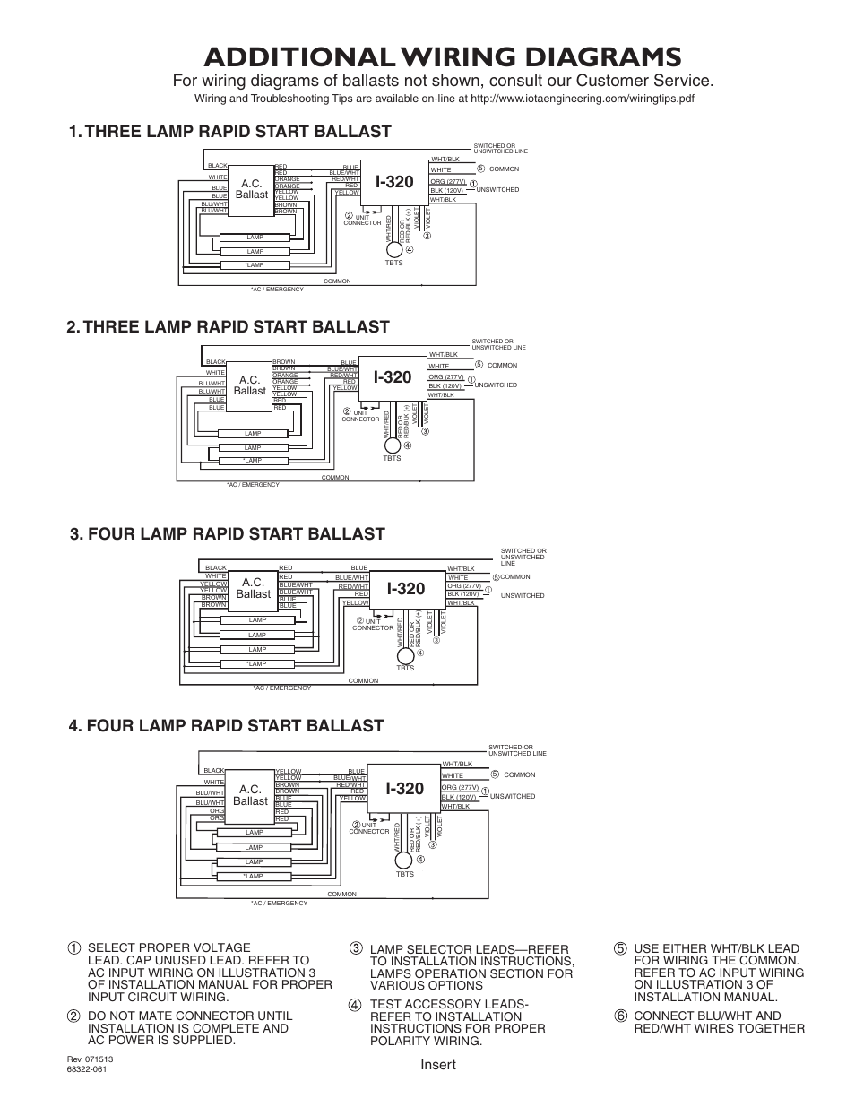
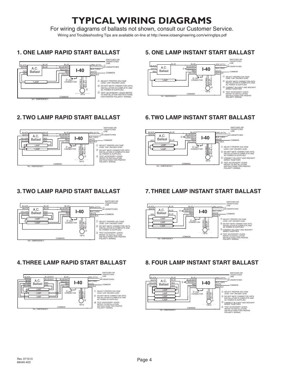
THE EMERGENCY BALLAST WIRING GUIDE This Document has been customized to contain a wide library of individual dia-grams for various installation applications. If a diagram cannot be found within this selection, consult Customer Service. The diagrams are categorized primarily according to the number of lamps in the fixture, then followed by the ballast type. Sometimes a specific lamp type is ...

A guide to emergency ballast for led and fluorescent lamps sanforce elp alternate wiring diagrams hatch lighting universal everline eld10unvl driver 10 watt 90 minute battery backup fixtures 120 277v input voltage 15 50vdc output class 2 at green electrical supply eld20unvl highbays 20 espen technology inc watts max 25 48v jen whole keystone kt emrg 5 500… Read More »
C. When the EMERGENCY BALLAST is used with a switched fixture, the A.C. Input to the BALLAST must be connected ahead of the fixture switch. Refer to IIIustration 3 for switched and unswitched fixture wiring diagrams. EMERGENCY BALLAST IIIustration 1 IIIustration 2 Recessed Troffer Fixture Strip Fixture EMERGENCY BALLAST FIXTURE BALLAST CHANNEL ...
Variety of power sentry emergency ballast wiring diagram. A wiring diagram is a simplified conventional pictorial representation of an electrical circuit. It shows the elements of the circuit as simplified forms, and the power as well as signal links in between the devices. A wiring diagram usually gives info about the relative position and also plan of devices and also terminals on the tools ...
Emergency Ballast Troubleshooting. Emergency ballast wiring can be very complex and difficult to troubleshoot. Some electricians really struggle with them and replace the whole fixture rather than try to figure out where the problem is. The standard ballast has a wiring diagram on it, but an emergency ballast has many possible diagrams that are ...
and battery connector of the emergency ballast before servicing. ... Refer to the wiring diagrams on the back page for the appropriate wiring of lamp(s)and ...5 pages
This video is about Emergency Ballast Replacement highlights

1. Disconnect AC power from the fixture Remove the ballast channel cover and install the emergency ballast either in the ballast channel (see Illustrations 1 & 2) or on top of the fixture* (see Illustration 3). 2. Select the appropriate wi ing diagram to connect the emergency ballast to the AC ballast and lamp Make sure

Lithonia Emergency Ballast Wiring Diagram Sample. Variety of lithonia emergency ballast wiring diagram. A wiring diagram is a simplified conventional photographic depiction of an electric circuit. It shows the elements of the circuit as streamlined forms, as well as the power as well as signal connections between the tools.

facturer is listed for AC ballasts that have unique wiring arrangements. Diagrams for specific situations can be located within this PDF file by using the following methods: 1) USING THE NAVIGATION WINDOW Use the Navigation window and select the Emergency Ballast for which the diagram is needed, then scroll through the list of applications to ...

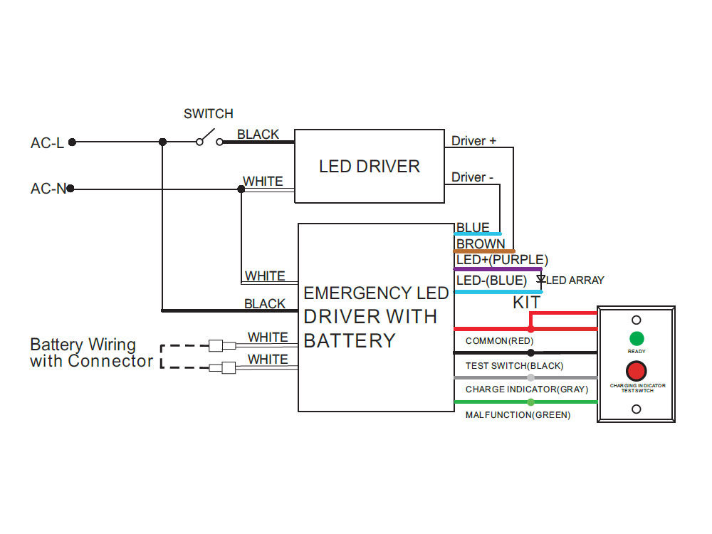
AC power to the emergency ballast. 9. The battery needs to be charged for one hour in order to have short-term testing on the emergency function. Before having a long-term emergency function testing, the battery in the emergency ballast has to be charged for 24 hours. DIAGRAM 2 Test Switch Charging Indicator Light Emergency Ballast Charging ...

THE EMERGENCY BALLAST WIRING GUIDE This Document has been customized to contain a wide library of individual dia-grams for various installation applications. If a diagram cannot be found within this selection, consult Customer Service. The diagrams are categorized primarily according to the number of lamps in the fixture, then followed by the ballast type. Sometimes a specific lamp type is ...
Fluorescent Emergency Ballast Wiring Diagram Sample. fluorescent emergency ballast wiring diagram - A Novice s Overview to Circuit Diagrams A very first consider a circuit diagram could be confusing, yet if you could review a train map, you could read schematics. The function coincides: obtaining from point A to aim B. Literally, a circuit is the…
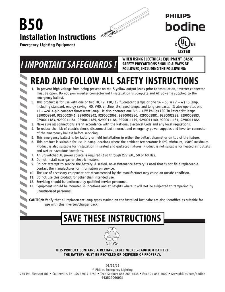
Size: 1.02 MB. Dimension: 2432 x 3507. Assortment of bodine b50 wiring diagram. Click on the image to enlarge, and then save it to your computer by right clicking on the image. Electronic Ballast Wiring Diagram Fluorescent Ballast Wiring Diagram. Bodine Emergency Ballast Wiring Diagram Electrical Drawing. Emergency Relay Wiring Diagram New ...
> Select the appropriate wiring diagram on back to connect the emergency ballast to the AC ballast and lamp(s). Make sure all connections are in accordance with the National Electrical Code and any local regulations. > After installation is complete, supply AC power to the emergency ballast and join the inverter connector.
The diagrams are categorized primarily according to the number of lamps in the fixture, then followed by the ballast type. Sometimes a specific lamp type is.299 pages
DOWNLOAD. Wiring Diagram Pictures Detail: Name: iota i 24 emergency ballast wiring diagram - Medium Size of Wiring Diagram Philips Advance Ballast Wiring Diagram Elegant Exelent T5 Ballast Wiring. File Type: JPG. Source: nezavisim.net. Size: 152.02 KB. Dimension: 728 x 456. DOWNLOAD. Wiring Diagram Images Detail:
Emergency ballast wiring diagram. Literally a circuit is the path that enables electrical energy to circulation. A wiring diagram is a streamlined standard photographic representation of an electrical circuit. It shows the components of the circuit as simplified forms and the power and signal links in between the devices. A very first consider a circuit diagram could be confusing yet if you ...
INSTRUCTIONS FOR PROPER POLARITY WIRING. ... TWO LAMP ELECTRONIC BALLAST. EMERGENCY. BALLAST. 2LEB. RED OR. RED/BLK(+). ➂. SELECT PROPER VOLTAGE LEAD.

Iota Emergency Ballast Wiring Diagram from diagramweb.net. Print the electrical wiring diagram off in addition to use highlighters in order to trace the signal. When you employ your finger or even the actual circuit together with your eyes, it's easy to mistrace the circuit. One trick that I 2 to print exactly the same wiring picture off twice.


0 Response to "44 emergency ballast wiring diagram"
Post a Comment