44 draw the shear diagram for the beam. follow the sign convention. (figure 1)
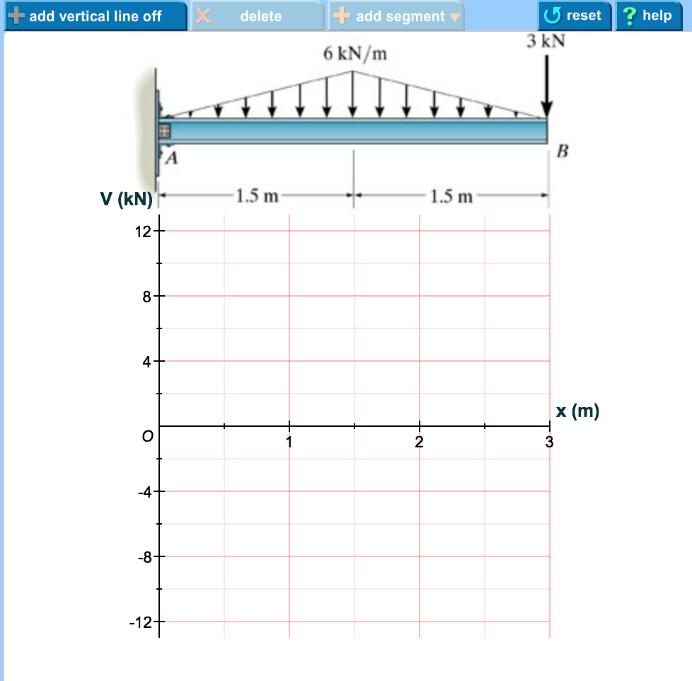
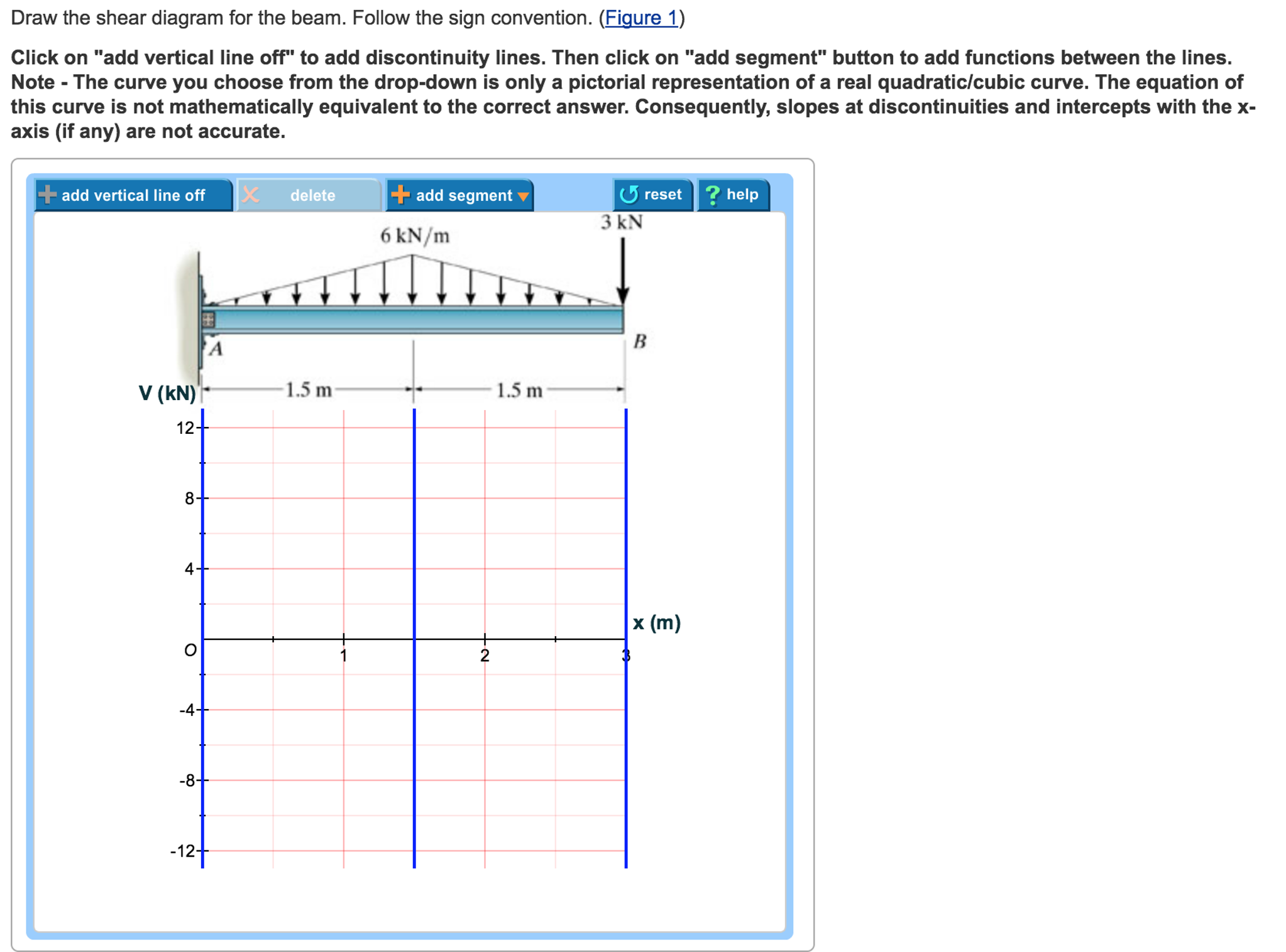
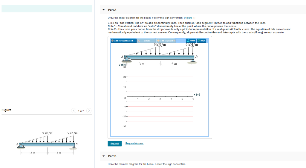
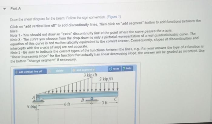
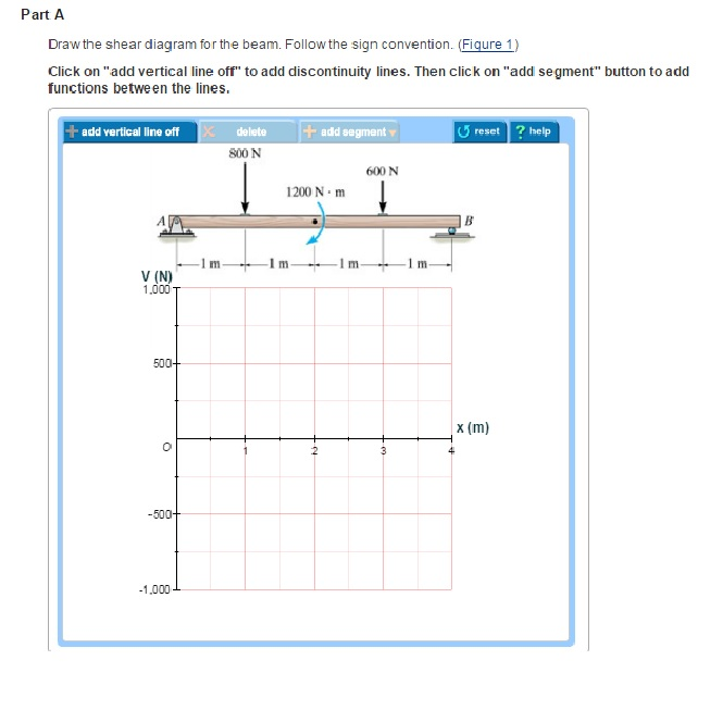
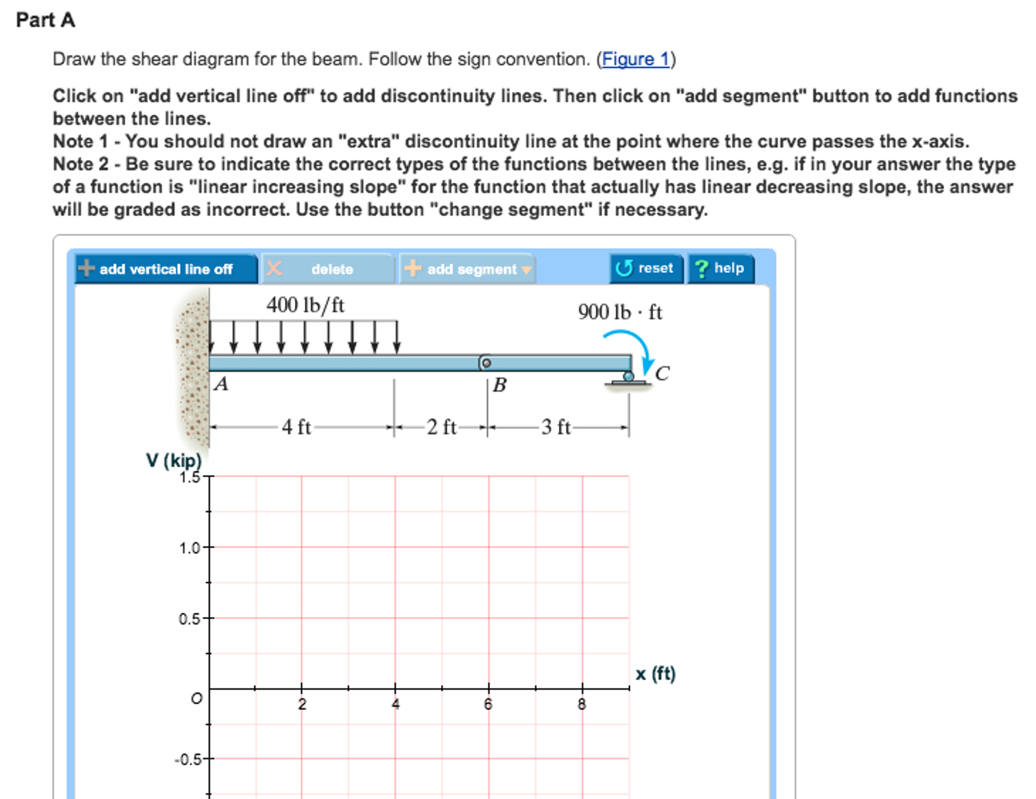
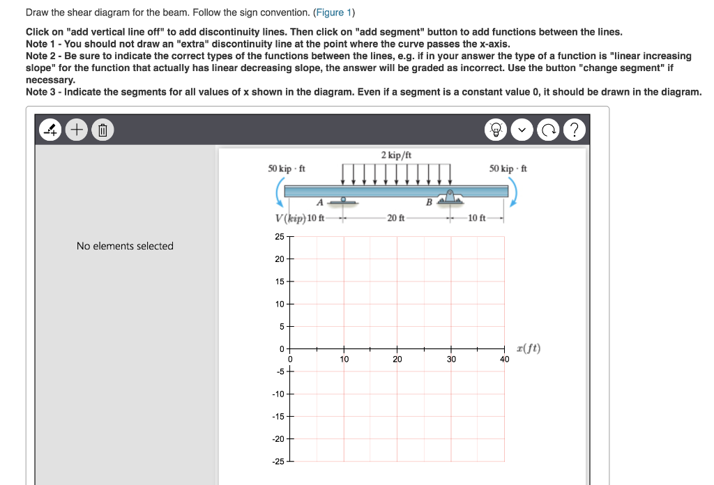
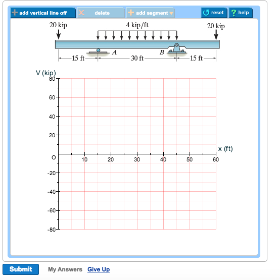
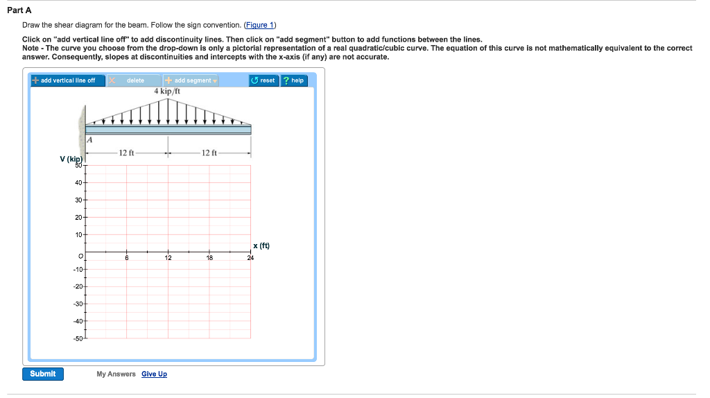
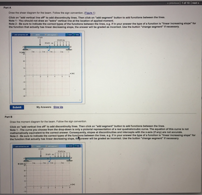
Draw the shear diagram for the beam. Follow the sign convention. (Figure 1) Click on "add vertical line off" to add discontinuity lines. Then click on "add segment" button to add functions between the lines. Note 1 - You should not draw an "extra" discontinuity line at the point where the curve passes the x-axis. Question: Draw the shear and moment diagram for the beam.Problem 7-71 from:Engineering Mechanics: Statics, 14th editionRussell C. HibbelerThank you guys for ...
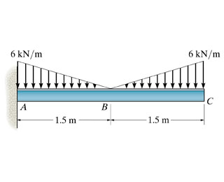
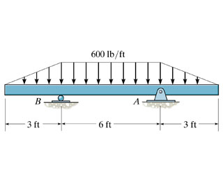
Draw the shear and moment diagrams for the beam shown in Fig. 6-7a. (a) L w 0 w —— 2 0 L (b) 2- L 3 w —— 2 0 L — 3 w 0 L2 w 0 Solution Support Reactions.The distributed load is replaced by its resultant force and the reactions have been determined as shown in Fig. 6-7b. Shear and Moment Functions.A free-body diagram of a beam ...

Draw the shear diagram for the beam. follow the sign convention. (figure 1)
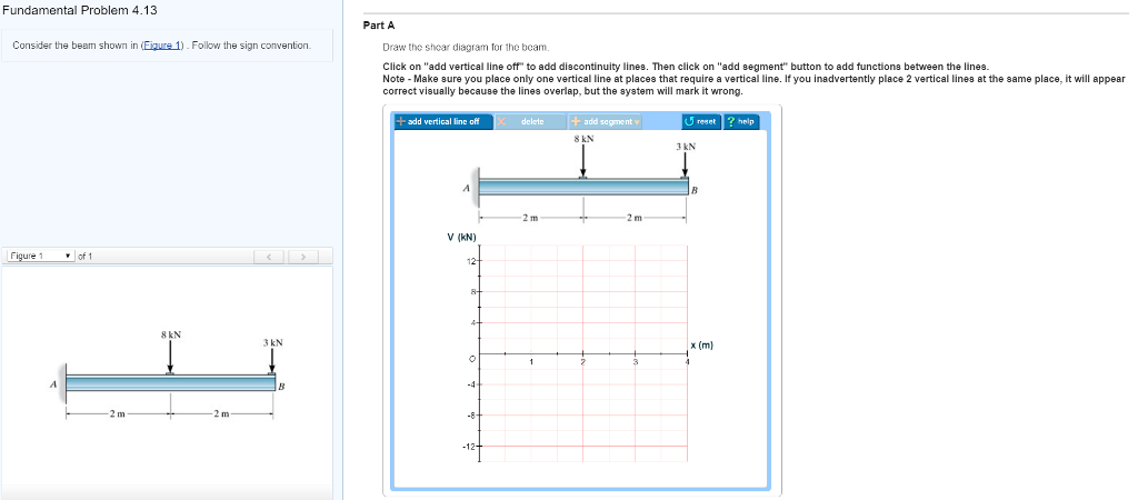
Answer (1 of 2): EDIT 2020-09-14 Without explaining all the calculus to prove it, a simple rule of thumb is: 1. the change in shear = -(area under the load curve (w)) 2. slope of the V curve = -(w) 3. slope of the M curve = V 4. the change in M = area under the V curve. Here's how I got my numb... Consider the beam shown in (Figure 1) . Follow the sign convention. Draw the shear diagram for the beam. Draw the moment diagram for the beam. Fundamental Problem 4.13 Considor tho beam shown in Eguro 10. Follow tho sign convention. 2 m 2 m Part A... shear force and bending moment and also some basic concepts of strength of materials in our recent posts. We have already seen the various types of beams and different types of loads on beam during our previous posts. Today we will see here the sign conventions for shear force and bending moment diagram in subject of strength of materials with the help of this post.
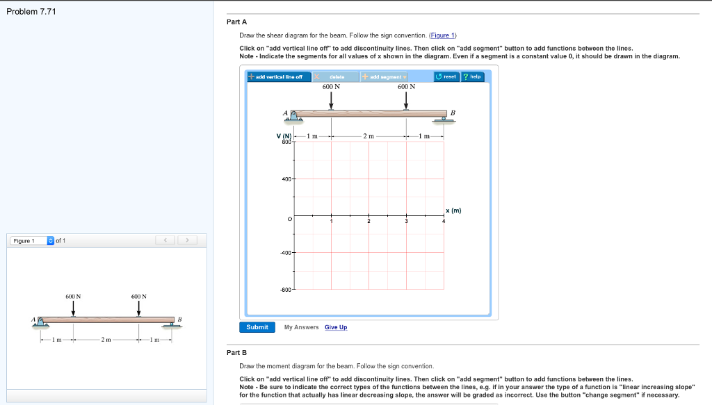
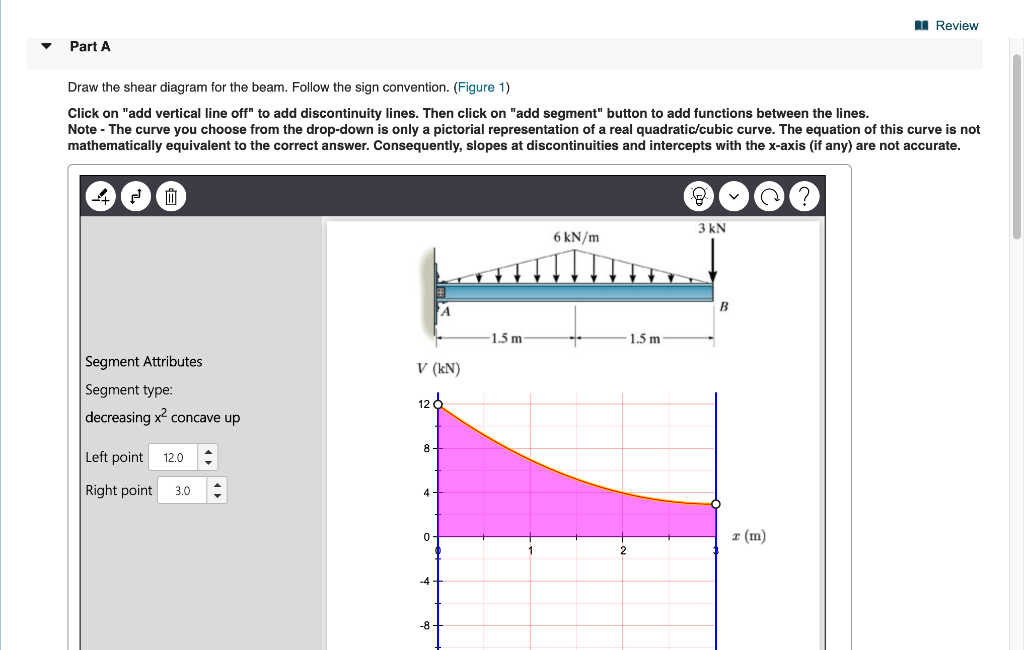
Draw the shear diagram for the beam. follow the sign convention. (figure 1). Oct 14, 2021 · Figure 1 click on add vertical line off to add discontinuity lines. Draw the shear and moment diagrams for the beam. (figure 1).How to draw shear force and bending moment diagrams strength of note 1 you should not draw an extra discontinuity line at the point where the curve passes the x axis. Part A Draw the shear diagram for the beam. Follow the sign convention. (Figure 1) Click on "add vertical line off" to add discontinuity lines. Then click on "add segment" button to add functions between the lines. Note 1 - You should not draw an "extra" discontinuity line at the point where the curve passes the x-axis. Draw the shear diagram for the beam. Follow the sign convention. (Figure 1) Click on "add vertical line off" to add discontinuity lines. Then click on "add segment" button to add functions between the lines. Note 1 - Make sure you place only one vertical line at places that require a vertical line. Jul 07, 2021 · Solved part a draw the shear diagram for the beam follow figu of part a draw the shear diagram for the beam. Draw the shear diagram for the beam. follow the sign convention. If there is an upward force ie a support then the sfd will start at this force above the x axis. Draw the shear and the moment diagrams for the beam shown in the figure.
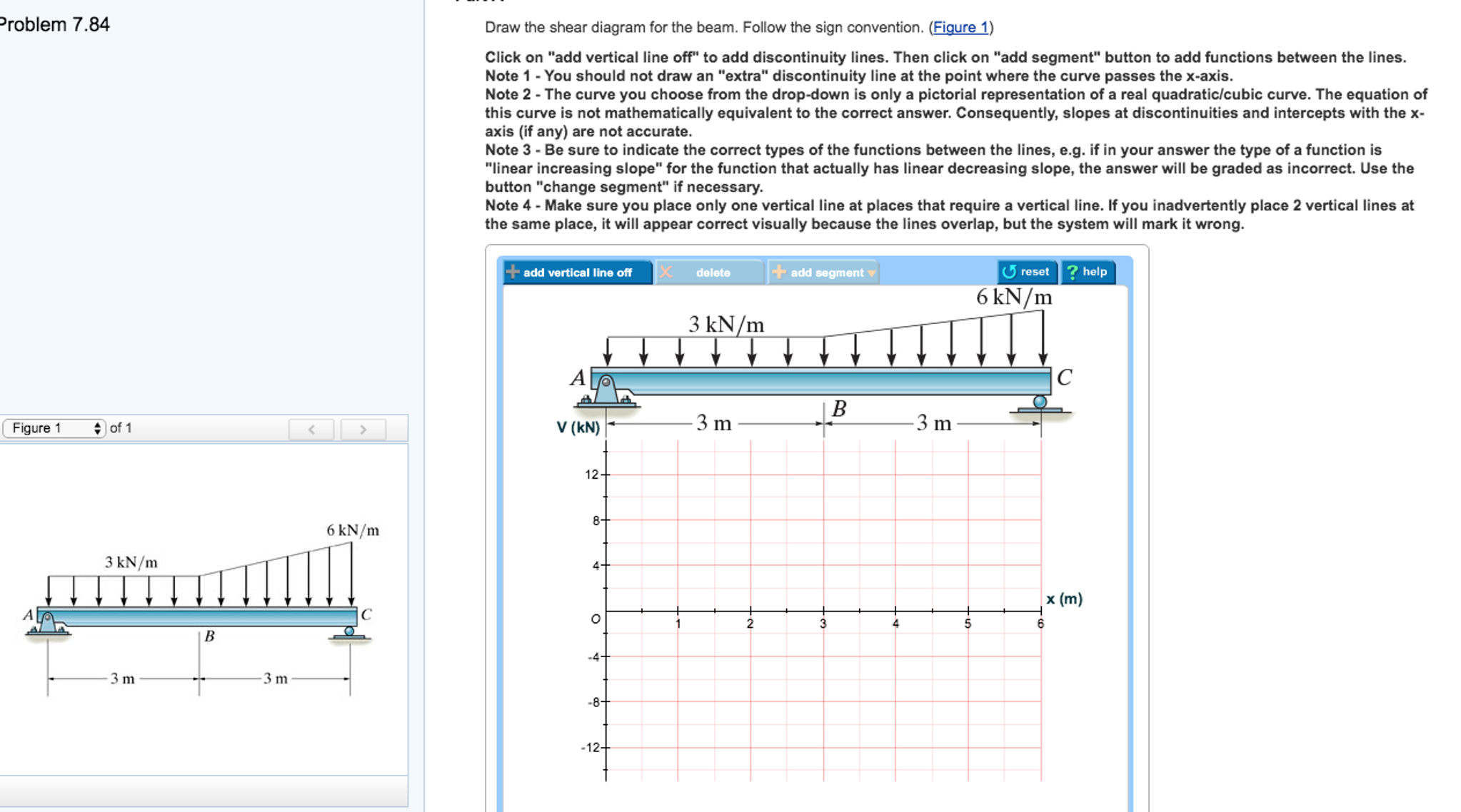
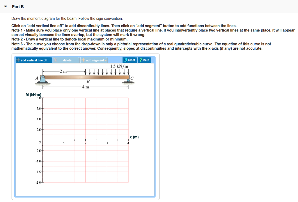
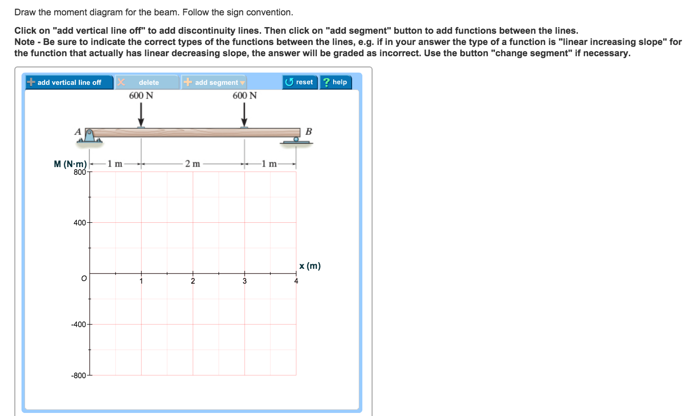
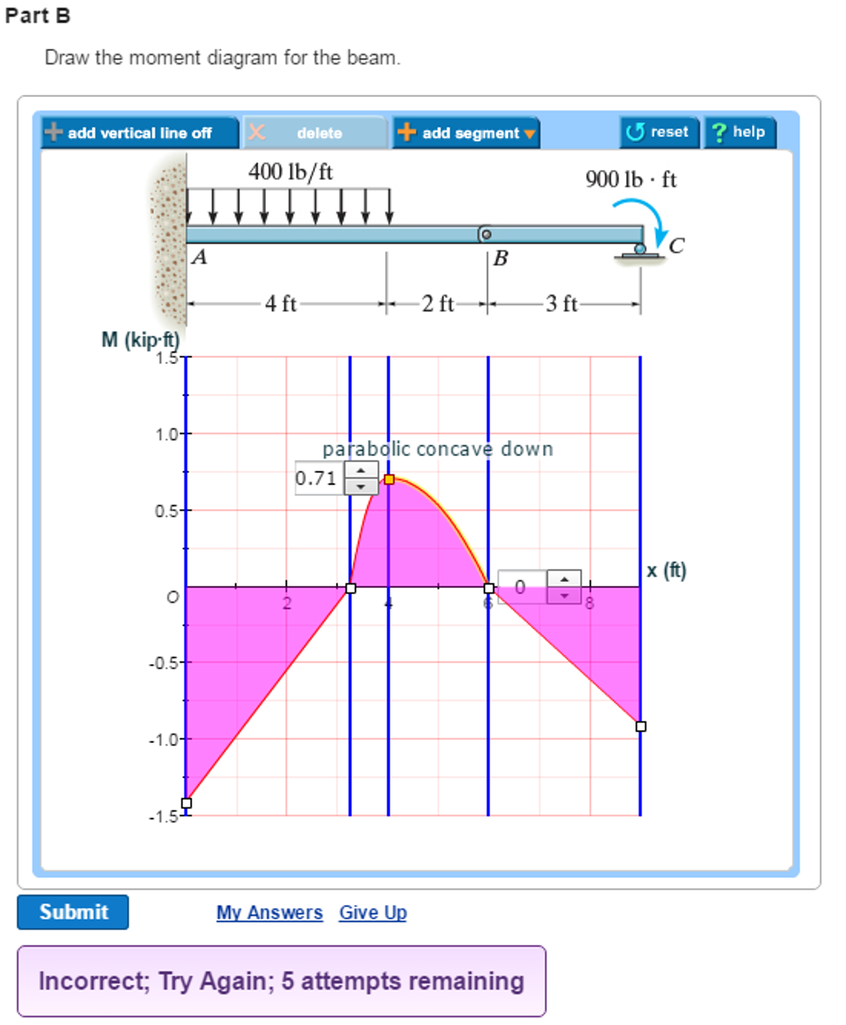
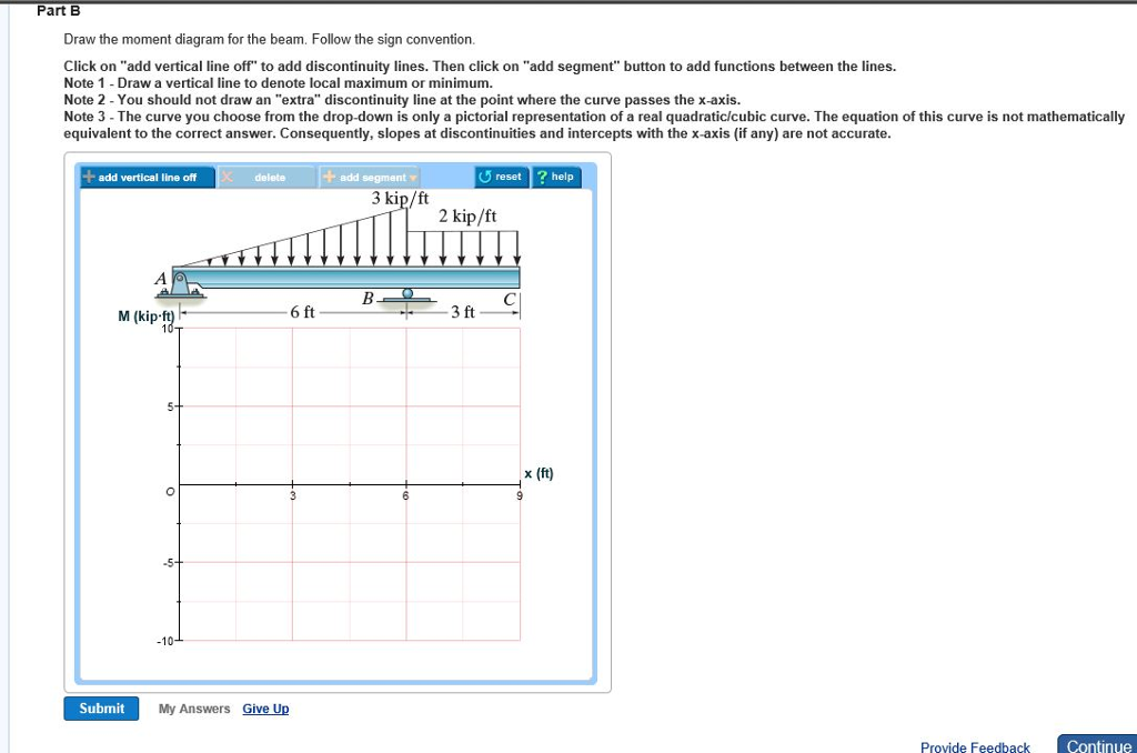
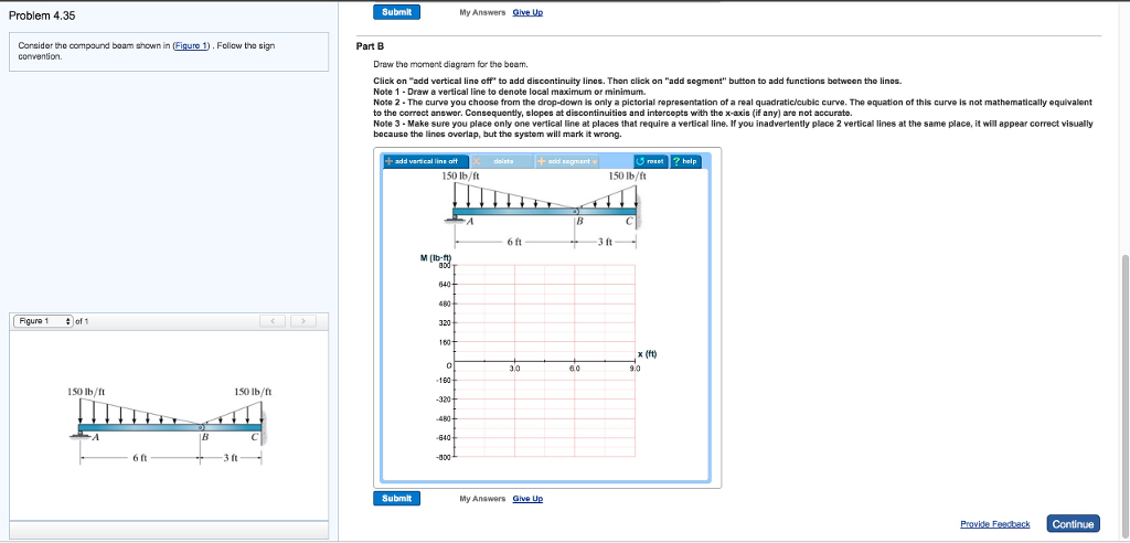
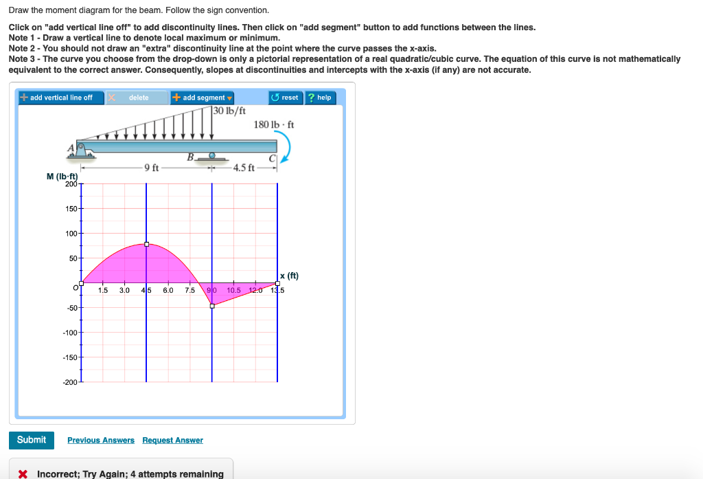
Problem 7.84 Draw the moment diagram for the beam. Follow the sign convention. Click on "add vertical line off" to add discontinuity lines. Then click on "add segment" button to add functions between the lines. Note 1 - Draw a vertical line to denote local maximum or minimum. Consider the beam shown in (Figure 1). Follow the sign convention. Draw the moment diagram for the beam. Click on "add vertical line off" to add discontinuity lines. Then click on "add segment" button to add functions between the lines. Note 1 - Draw a vertical line to denote local maximum or minimum. Civil Engineering. Civil Engineering questions and answers. Problem 7.77 Part A Draw the shear diagram for the beam. Follow the sign convention. (Figure 1) Click on "add vertical line off" to add discontinuity lines. Then click on "add segment" button to add functions between the lines Note 1- You should not draw an "extra" discontinuity line at the point where the curve passes the x-axis Note 2 Be sure to indicate. Draw the shear diagram for the beam follow the sign convention. 12 shear and moment functions. Draw the shear diagram for the beam. Figure 1 part b. Follow the sign convention click on add vertical line off to add discontinuity lines. Follow the sign convention. Draw the shear and moment diagrams for the compound beam shown in the figure.
Problem 7.80 3 of 3 Draw the shear diagram for the beam. Follow the sign convention. (Figure 1) Click on "add vertical line off" to add discontinuity lines. Then click on "add segment" button to add functions between the lines. Note 1 You should not draw an "extra" discontinuity line at the point where the curve passes the x-axis. The positive sign convention consistent with beam theory is shown in F.1(b). As seen from F.1 (b), the positive sign convention is (a) tension axial force, (b) shear forces that produce clockwise moments and (c) bending moments that result in tension stresses in the interior frame fibers. The sign convention of F.1(b) can shear force and bending moment and also some basic concepts of strength of materials in our recent posts. We have already seen the various types of beams and different types of loads on beam during our previous posts. Today we will see here the sign conventions for shear force and bending moment diagram in subject of strength of materials with the help of this post. Consider the beam shown in (Figure 1) . Follow the sign convention. Draw the shear diagram for the beam. Draw the moment diagram for the beam. Fundamental Problem 4.13 Considor tho beam shown in Eguro 10. Follow tho sign convention. 2 m 2 m Part A...
I AM BOLD
Answer (1 of 2): EDIT 2020-09-14 Without explaining all the calculus to prove it, a simple rule of thumb is: 1. the change in shear = -(area under the load curve (w)) 2. slope of the V curve = -(w) 3. slope of the M curve = V 4. the change in M = area under the V curve. Here's how I got my numb...
Solved: Part A Draw The Shear Diagram For The Beam. Follow ...

Neon love sign
Solved: Part A Draw The Shear Diagram For The Beam. Follow ...
Wiring Diagram: 7 Draw The Shear Diagram For The Beam ...
Solved: Draw The Shear Diagram For The Beam. Follow The Si ...

Solved: Part A Draw The Shear Diagram For The Beam. Follow ...
Solved: Part Draw The Shear Diagram For The Beam. Follow T ...
Solved: Problem 7.84 Figure 3 M 6 KN /m Draw The Shear Dia ...
Solved: Problem 7.56 ? Part A Draw The Shear Diagram For T ...
Solved: Part A Draw The Shear Diagram For The Beam. Follow ...
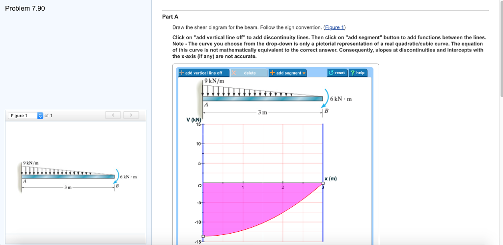
Solved: Problem 7.90. Draw The Shear Diagram For The Beam ...

With All Your Heart 2
Solved: Draw The Shear Diagram For The Beam. Follow The Si ...

Hola sign
Solved: Draw The Shear Diagram For The Beam. Follow The Si ...

Draw The Shear Diagram For The Beam Follow The Sign ...
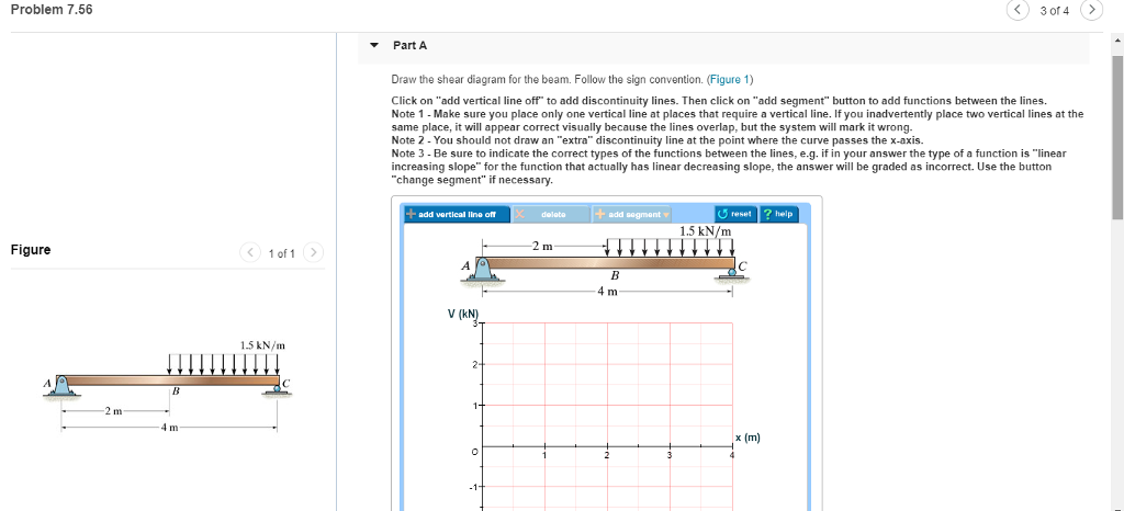
Solved: Problem 7.56 3 Of 4 Part A Draw The Shear Diagram ...
Solved: Draw The Shear Diagram For The Beam. Follow The Si ...
Solved: Part A Draw The Shear Diagram For The Beam. Follow ...

Draw the shear diagram for the beam shown in the figure ...
Solved: A) Draw The Shear Diagram For The Beam. Follow The ...
Draw The Shear Diagram For The Beam Follow The Sign ...
Solved: Draw The Shear Diagram For The Beam. Follow The Si ...

Good news is coming

Draw the shear and moment diagram of the beam. Following ...
Solved: Problem 7.64 Part A Draw The Shear Diagram For The ...
Solved: Problem 7.71 Part A Draw The Shear Diagram For The ...

Sunset Strip sidewalk sign

Happily ever after sign
Solved: Consider The Compound Beam Shown In (Figure 1) . F ...
Solved: Draw The Shear Diagram For The Beam. Follow The Si ...
Solved: Draw The Shear Diagram For The Beam. Follow The Si ...

For the figure below, draw: a) Draw the shear diagram for ...
Solved: Part A Draw The Shear Diagram For The Beam. Follow ...
Solved: Draw The Shear Diagram For The Beam. Follow The Si ...
Solved: Draw The Shear Diagram For The Beam Follow The Sig ...
Solved: Draw The Shear Diagram For The Beam. Follow The Si ...

Solved: Draw The Shear Diagram For The Beam. Follow The Si ...
Solved: Review Part A Draw The Shear Diagram For The Beam ...

I was in #MWC18 for 4 days. I was looking for a different perspective of technology and innovation. A human point of view.
Solved: A) Draw The Shear Diagram For The Beam. Follow The ...

Draw The Shear Diagram For The Beam Follow The Sign ...

Photo was taken at a Switchfoot concert in San Diego, California.
0 Response to "44 draw the shear diagram for the beam. follow the sign convention. (figure 1)"
Post a Comment