41 hvac condenser wiring diagram
PDF Standard AC with Standard Furnace Control Wiring Standard A/C Condenser AC Contactor 4 This diagram is to be used as reference for the low voltage control wiring of your heating and AC system. Always refer to your thermostat or equipment installation guides to verify proper wiring. NOTE Some AC Systems will have a blue wire with a pink stripe in place of the yellow or Y wire. Thermostat Wiring Diagrams Quality HVAC Guides 101 Thermostat Wiring Diagrams for Heat Pumps - Heat Pump Thermostat Wire Diagrams. Heat pumps are different than air conditioners because a heat pump uses the process of refrigeration to heat and cool.While an air conditioner uses the process of refrigeration to only cool, the central air conditioner will usually be paired with a gas furnace, an electric furnace, or some other method of heating.
Troubleshooting Your Mitsubishi Mini Split | HVACDirect.com Air Conditioner Condenser Units . Heat Pump Systems. Dual Fuel Heat Pump & Furnace Systems. Heat Pump Condensers. Air Conditioning Systems . Packaged & Rooftop Units. Room, Window & Portable A/C Units . Air Handlers for Central Air . Accessories. PTAC Units. Commercial HVAC Units. AIR CONDITIONERS . 1.5 Ton Air Conditioners. 2 Ton Air …

Hvac condenser wiring diagram
Heil Condenser Wiring Diagram - U Wiring Wiring Diagram Pics Detail. HVAC Compressor-Condenser Fan Motor Replacement Wiring. Single-stage two-stage and variable capacity. The latest local weather crime politics events and more. BLACK - to a control box. The fan in the outdoor unit still runs. Jan 01 1978 This catalog is packed with a variety of radios. Ac Condenser Fan Motor Wiring Diagram 4 Wire Beautiful For ... Nov 27, 2019 - Ac Condenser Fan Motor Wiring Diagram 4 Wire Beautiful For New 7 Understand Basic HVAC Electrical Components & Wiring in ... To keep track of wiring, HVAC technicians rely on circuit schematics or visual representations of wiring programs. There are three basic types of circuit schematics used in HVAC today. They are the Line Diagram, the Ladder Diagram, and the Installation Diagram. You can think of these circuit schematics as road maps. Instead of roads, there are wires that travel from electrical …
Hvac condenser wiring diagram. Ac Condenser Fan Motor Wiring Diagram | Fuse Box And ... Description : Condenser Fan Motor Wiring Diagram in Ac Condenser Fan Motor Wiring Diagram, image size 600 X 559 px, and to view image details please click the image. Here is a picture gallery about ac condenser fan motor wiring diagram complete with the description of the image, please find the image you need. Basic Air Conditioner Wiring Diagram - U Wiring How to read AC or air conditioner condenser unit wiring diagram schematic. 3- Types of Electrical Wiring Diagrams For Air Conditioning Systems. Basic Thermostat Wiring Colors - Air Conditioner Systems - Always remember when changing a thermostat for a new thermostat to take a photo of the colors and where they go on the old thermostat or ... PDF HVAC Condenser Motor Replacement Wiring Guide Move the brown wire from the "F" ... Added Jumper 2MEV9 Step 2 L1 L2 208-230 VAC L1 L2 208-230 VAC L1 L1 Common L2 L2 L2 Brown (Common) Title: HVAC-Condenser-Fan-Motor-Wiring-Diagram Author: xdxg012 Created Date: 5/24/2018 11:26:51 AM ... Ac Compressor Wiring Diagram - The Wiring Ac low voltage wiring diagram. Compressor and fan motor furnished with inherent thermal protection. AC System Diagram Before you call a AC repair man visit my Air conditioning unit wiring diagrams fig. Ac compressor wiring diagram. 1—38ck018 (32, 34), 38ck(m)024 (32, 34), 38ck(m)030 (30, 32), 38ck(m)036. Each part should be placed and linked to other […]
Wiring Diagram Tracing - Older RHEEM Condenser - HVAC School Wiring Diagram Tracing - Older RHEEM Condenser. Bryan explains how to read schematics/diagrams on HVAC equipment and walks through an example. He takes a Rheem air conditioner and compares the physical unit to its point-by-point diagram and ladder schematic. By Bryan Orr. Point-to-point diagrams illustrate how each component is wired in a ... Electrical Wiring Diagrams for Air Conditioning Systems ... 1- Importance Of Electrical Wiring For Air Conditioning Systems. In the detailed design phase, the electrical designer must size and select the wires/cables, conduits, starters, disconnects and switchgear necessary for supplying power and control to HVAC equipment. This information designed by the electrical designer will be and must appear on ... Electric Motor Reset Button - motor overload reset switch How to find and reset the thermal overload switch found on many electric motors Tips for Finding the Motor Reset Button How to reset the motor switch on a furnace or air conditioner blower fan unit What the Reset Button Looks Like When it has Not Tripped Some Electric Motors Include an Automatic Thermal Reset SwitchHow to reset the motor switch on water pumps and well … HVAC Plan Symbols and Their Meanings - EdrawMax - Edrawsoft 2021-07-21 · HVAC (heating, ventilation, and air conditioning) plans refer to the drawings made by specialized engineers that include all the details needed to create, set up, and maintain the heating and cooling system in a building.. The HVAC plans are quite important and are developed once the building's floor plans have been completed. The engineers use their expertise to …
Amana & Goodman HVAC Manuals, Parts Lists, Wiring ... Manuals, parts lists, wiring diagrams for Goodman & Aman a HVAC equipment: Free downloadable manuals for Air Conditioners, Boilers, Furnaces, Heat Pumps. Here we provide free downloadable copies of installation and service manuals for heating, heat pump, and air conditioning equipment, or contact information for the manufacturer. We also provide an … Trane Condenser Fan Motor Wiring Diagram - schematron.org Trane Condenser Fan Motor Wiring Diagram. Rheem-Ruud Condenser Fan Motor wiring diagram heat pump wiring diagram blower motor wiring heat pump parts ruud air conditioning trane. Orange wire that is the start winding for compressor that goes on HERM. Red wire from contactor goes to C on capacitor, purple from fan goes to C on capacitor. PDF WIRING DIAGRAM - Nortek Global HVAC Split System Heat Pump (Outdoor Section) Single Phase NOTES: 1. Disconnect all power before servicing. 2. For supply connections use copper conductors only. Ac Condenser Wiring Diagram - Wirings Diagram Ac Condenser Wiring Diagram - ac condenser contactor wiring diagram, ac condenser fan motor wiring diagram, ac condenser fan wiring diagram, Every electric arrangement consists of various different components. Each component should be set and linked to different parts in specific manner. If not, the arrangement won't function as it should be.
Bryant 127A Preferred™ 2-Stage Air Conditioner Wiring diagram ...
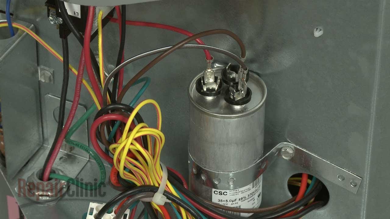
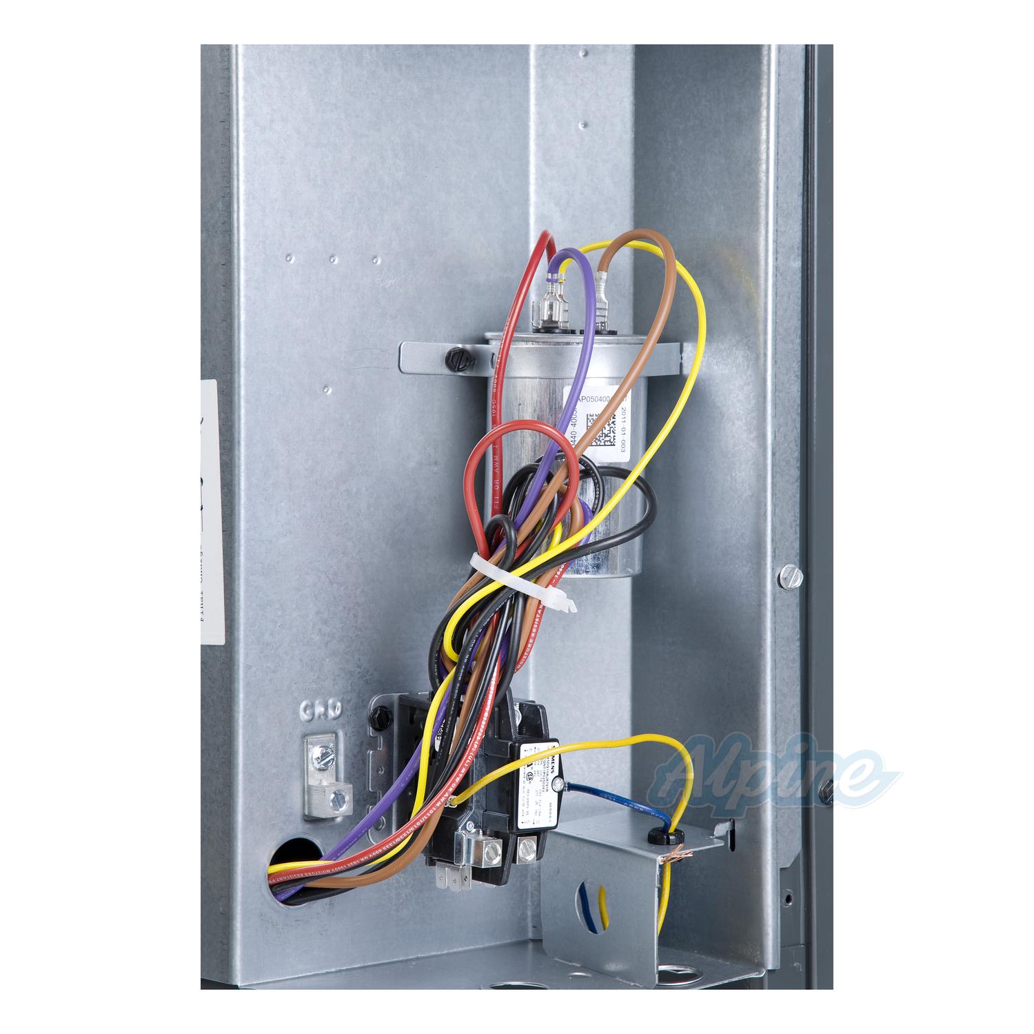
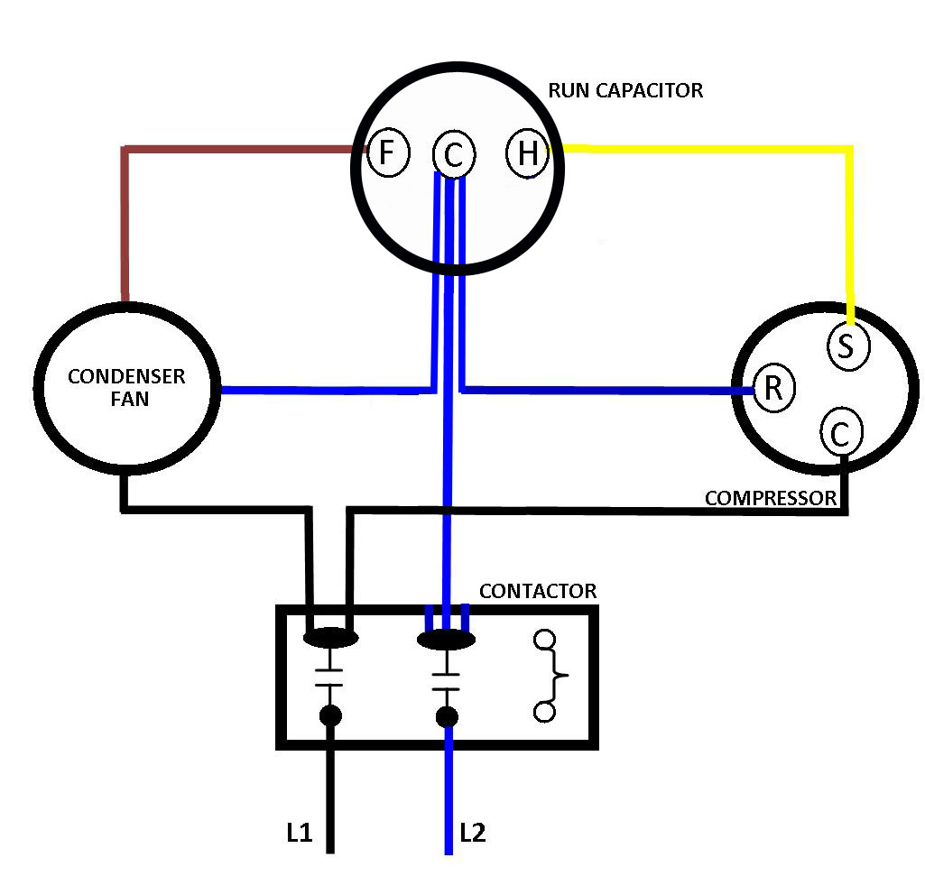
Condenser Capacitor Wiring Diagram - easywiring Hvac condenser fan motor wiring diagram. How to wire a run capacitor to a motor blowers condensers sometimes when a blower or condenser fan motor goes bad a technician or even a diyer has issues wiring the new motor and capacitor most motors come with clear instructions or a wiring diagram on the side. Examine and understand the condensing unit ...
York Central Air Conditioner Won't Run? #S1-02423998700
Wiring Diagram: 24 Volt Transformer Wiring Diagram 24 Volt ... 24 Volt Transformer Wiring Diagram with Air Handler and Condenser, 24 Volt Transformer Wiring Diagram with Thermostat and Compressor Contractor, Chime and 24 Volt Transformer Wiring Diagram with Front Button. Doorbell and 24 Volt Transformer Wiring Diagram with Push Button, High Limit Safety and 24 Volt Transformer Wiring Diagram with Fan Relay, HVAC Control Unit
Electrical Specs for Installing Ductless Mini-Splits & HVAC Units
How To Wire an Air Conditioner Condenser Outside Unit ... Quick video stepping you through how to wire a typical 220v AC condenser unit. Hope it helped you out! Please subscribe!Blessings,Ben
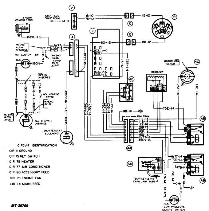
Fig. 17 Heater and Air Conditioner Wiring Diagram
3-Wire and 4-Wire Condensing Fan Motor ... - HVAC School Diagram courtesy of Emerson New techs have a common question of how to wire a condensing fan motor for 3 vs. 4 wires. Jesse Grandbois submitted this tech tip to help make it simple. Thanks, Jesse! This tech tip is a quick one on the difference between wiring universal condenser fan motors and why brown […]
Central Air Conditioner Parts: All About the Condenser ...
Wiring an Outdoor Condenser! What each of the Wires is For ... This is how to wire a 240-volt single-phase Condenser used for Air Conditioning. This includes where to install the high and low voltage wiring and why, how ...
Goodman GSX130241 2 Ton, 13 to 14 SEER Condenser, R-410A ...
Free Vehicle Repair Guides & Auto Part Diagrams - AutoZone Find out how to access AutoZone's Main Wiring Diagram (Equivalent To 'Standard Equipment') (Cabrio 1999) (1999) Repair Guide for Volkswagen Cars 2000-05. Read More . Cadillac Deville, Fleetwood, ELD, Seville 1990-1998 Fuses Repair Guide. Find out how to access AutoZone's Fuses Repair Guide for Cadillac Deville, Fleetwood, ELD, Seville 1990-1998. Read More . …
air Conditioning Thermostats -- How To Wire A Thermostat
5 Wire Condenser Fan Motor Wiring Diagram - Studying Diagrams HVAC Condenser Fan Motor Wiring Diagram. I need guidance on wiring a 5 wire universal condenser fan motor to a 3 wire condenser system. Sometimes the wires will cross. 3 Wire And 4 Condensing Fan Motor Connection Hvac School. 5 Wire Stator Wiring Diagram wiring diagram is a simplified good enough pictorial representation of an electrical ...

Air Conditioner Connection and Wiring Diagram - ETechnoG
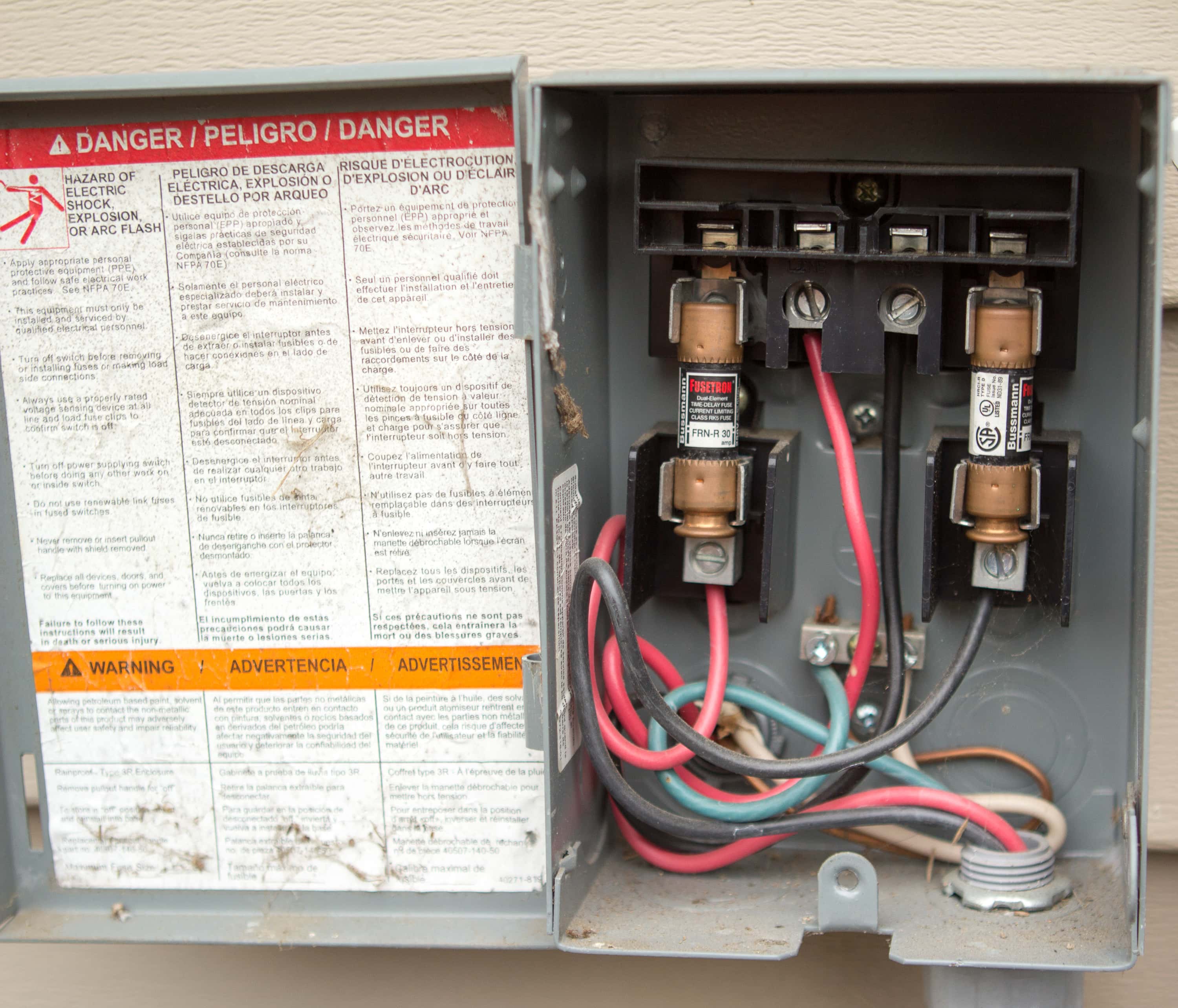
How to Wire an Outside AC Condenser | Hunker The high-voltage wires from the air conditioner disconnect box (usually mounted on an outside wall within arm's reach of the air conditioner unit) are now pushed up through the wire clamp in the bottom of the box. The high-voltage wires have two insulated power wires and one bare copper ground wire.

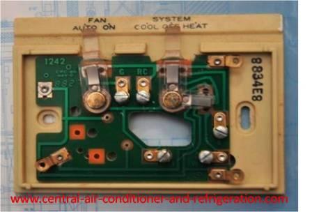
Thermost Wiring | AC Service Tech
How-To Wire Condenser Fan Motors Properly in 3-Wire & 4 ... For a visual picture of typical wiring configurations, reference the following guide: HVAC Condenser Fan Motor Wiring Diagram. Finally, this guide is intended to be used as a general overview of common condenser unit wiring schematics. Some condenser fan motors wire to a circuit board while others use proprietary plugs for their connectors.

I need a basic wiring diagram for an old Ruud heat pump/air ...
Hvac Wiring Diagrams Troubleshooting - The Wiring Hvac Condenser Wiring Diagram Valid Wiring Diagram for Ac Condenser. Nortek Global HVAC/Reznor does not endorse any field changes to factory wiring schemes. Assortment of trane furnace wiring diagram. Wiring Diagram for Bi Boiler Best Wiring Diagrams for Central. If you have a clear under-standing of how to read wiring diagrams, you fre-quently ...

Heat Pump Thermostat Wiring Chart Diagram Quality 101
Condenser Wiring Diagram - easywiring Wiring Diagram Symbols Chart Split Air Conditioner Wiring Diagram Hvac Condenser Wiring Diagram Fres . However some people still struggle with the wiring part of the motor to the capacitor. Condenser wiring diagram. With this sort of an illustrative manual you are going to be able to troubleshoot prevent and complete your assignments easily.
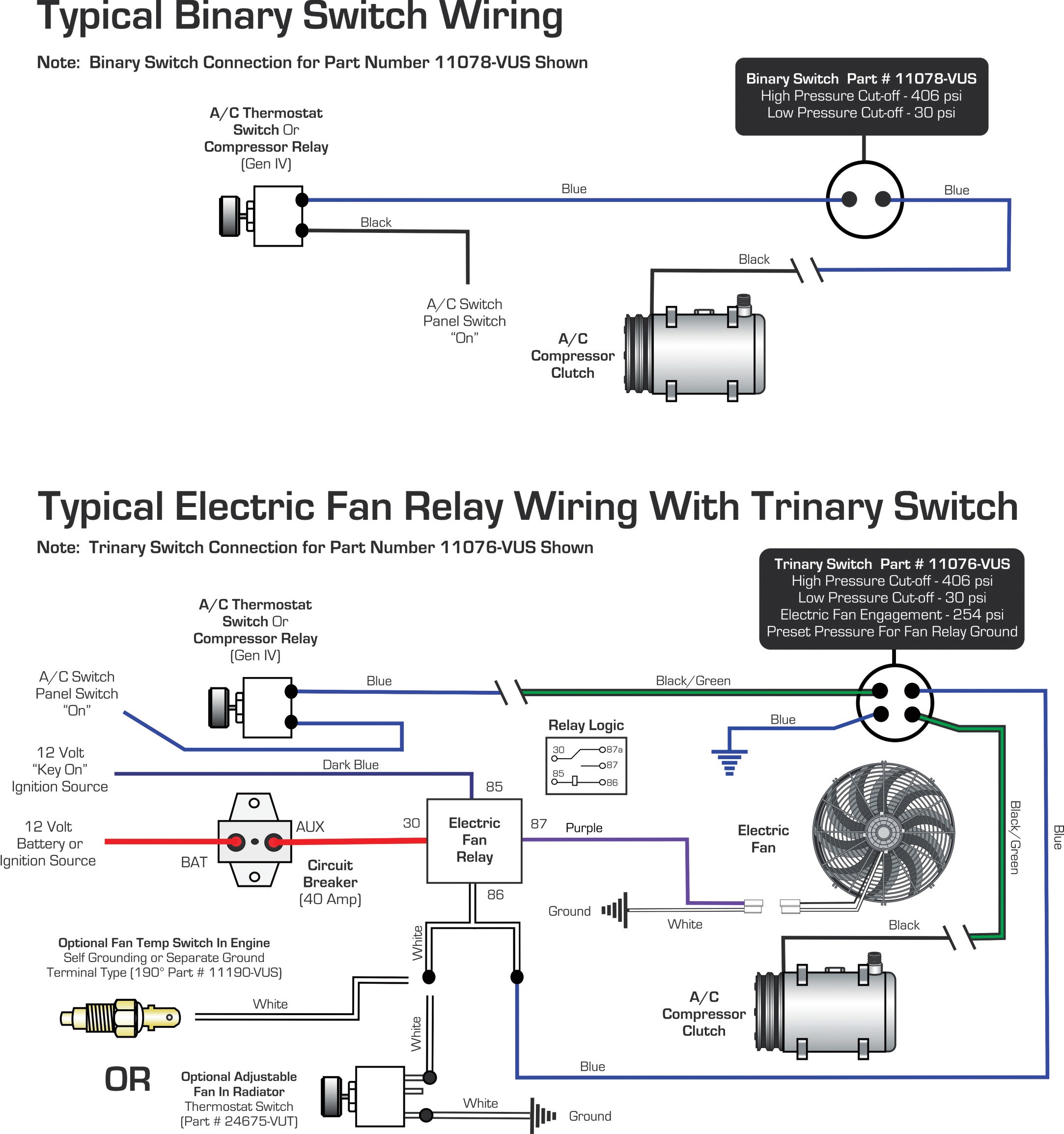
Vintage Air » Blog Archive WIRING DIAGRAMS Binary Switch ...
Why Compression Ratio Matters - HVAC School 2020-06-03 · Look at the pressure enthalpy diagram above. Top to bottom (vertical) is the refrigerant pressure scale; high pressure is higher on the chart. Horizontal (left to right) is the heat content scale; the further a value is right, the more heat contained in the refrigerant (heat, not necessarily temperature). Start at point #2 on the chart at the bottom right. That is where the …
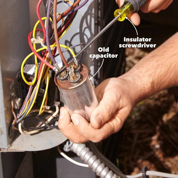
Can you use two single capacitors instead of one dual ...
How to Wire a Run Capacitor to a Motor Quality Wiring 101 How to Wire a Run Capacitor to a Motor Blower & Condenser HVAC Wiring. The above illustration does not cover every single type of motor wiring available on the market. However, the motor and capacitor diagram represents a vast majority of motors and capacitor wiring available to the general public. Additionally, we recommend you thoroughly read the instructions that …

WAZIPOINT Engineering Science & Technology: Most Useful HVAC ...
Ac Condenser Wiring Diagram - Cadician's Blog Ac Condenser Motor Wiring Diagram | Manual E-Books - Ac Condenser Wiring Diagram. Wiring diagram also offers beneficial suggestions for tasks which may demand some added equipment. This e-book even consists of ideas for added materials that you might require in order to end your projects. It will be in a position to offer you with extra ...

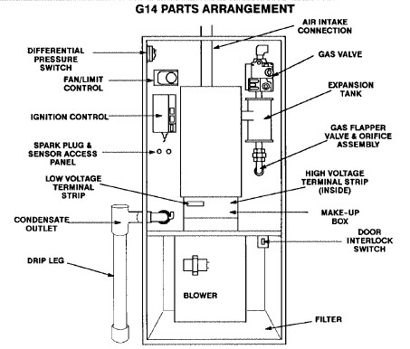
Diagram Page
How to Wire an Air Conditioner for Control 5 Wires Quality The question is: How to Wire an Air Conditioner for Control 5 Wires - The diagram below includes the typical control wiring for a conventional central air conditioning system.Furthermore, it includes a thermostat, a condenser, and an air handler with a heat source. Moreover, the heat source for a basic ac system can include heat strips for electric heat or even a hot water coil inside the ...

hvac - Furnace Mainboard wiring with AC unit - Home ...
Condenser Fan Wiring Diagram - wireschema.com The new motor should have come with a wiring diagram showing the connection options: 3-wire operation, 4-wire operation, and rotation direction.May 24, · For a visual picture of typical wiring configurations, reference the following guide: HVAC Condenser Fan Motor Wiring Diagram.

Air Conditioner Connection and Wiring Diagram - ETechnoG
Ac Condenser Unit Wiring Diagram - Wiring Diagram How to wire an air conditioner for control 5 wires the diagram below includes the typical control wiring for a conventional central air conditioning systemit includes a thermostat a condenser and an air handler with a heat source. Straight cool air conditioning condensing unit wiring practice. If not the arrangement wont function as it should be.
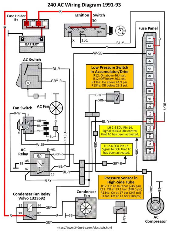
Dave's Volvo Page - Volvo 240: Classic Auto Air Retrofit
Wiring Diagram For Fedders A/c Condenser Fan Motor Since the #2 white wire is allways connected to the fan and compressor, since it Air conditioning works the same no matter what the applicatiion. auto, home, . "My original condenser fan motor has three wires and the replacement the following guide: HVAC Condenser Fan Motor Wiring Diagram.

How to Wire a Run Capacitor to a Motor Quality Wiring 101
PDF Standard AC Wiring Diagrams update - Alpine Home Air Standard A/C Condenser AC Contactor 4 This diagram is to be used as reference for the low voltage control wiring of your heating and AC system. Always refer to your thermostat or equipment installation guides to verify proper wiring. NOTE Some AC Systems will have a blue wire with a pink stripe in place of the yellow or Y wire.
How to replace condensor fan motor? | DIY Home Improvement Forum
Understand Basic HVAC Electrical Components & Wiring in ... To keep track of wiring, HVAC technicians rely on circuit schematics or visual representations of wiring programs. There are three basic types of circuit schematics used in HVAC today. They are the Line Diagram, the Ladder Diagram, and the Installation Diagram. You can think of these circuit schematics as road maps. Instead of roads, there are wires that travel from electrical …
Typical Field Wiring and Wiring diagram
Ac Condenser Fan Motor Wiring Diagram 4 Wire Beautiful For ... Nov 27, 2019 - Ac Condenser Fan Motor Wiring Diagram 4 Wire Beautiful For New 7

Ac Motor Kit Picture: Ac Motor Capacitor Wiring
Heil Condenser Wiring Diagram - U Wiring Wiring Diagram Pics Detail. HVAC Compressor-Condenser Fan Motor Replacement Wiring. Single-stage two-stage and variable capacity. The latest local weather crime politics events and more. BLACK - to a control box. The fan in the outdoor unit still runs. Jan 01 1978 This catalog is packed with a variety of radios.
Electrical Specs for Installing Ductless Mini-Splits & HVAC Units

Thermostat Wiring: How To Wire Thermostat? (2,3,4,5 Wire Guide)
HVAC condenser - how to read AC schematic and wiring diagram - air condition howto
AC Repair: How to Troubleshoot and Fix an Air Conditioner ...

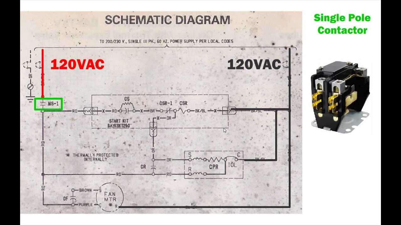
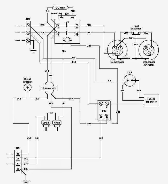
Basic Compressor Wiring
How to wire a 2 stage A/C unit with only 2 wires running outside.

How to Diagnose and Repair a Air Conditioner Capacitor ...

How to Wire an Air Conditioner for Control 5 Wires Quality
Air handler and condenser wiring please help | DIY Home ...
HVAC Manuals Wiring Diagrams FAQs on where to get

Capacitors For Compressor Wiring Diagram | Ac capacitor ...

Rear A/C condenser fan relay wiring diagram - Pelican Parts ...

Unique Single Phase Capacitor Start Capacitor Run Motor ...

Split AC Indoor To Outdoor Wiring Diagram

Wiring Diagram ng A/C Compressor at A/C Condenser Fan Motor
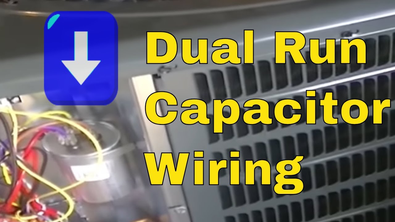
HVAC Training | Dual Run Capacitor Wiring

Electrical Wiring Diagrams for Air Conditioning Systems ...
Schematic Diagrams for HVAC Systems - Modernize
Thermostat Wiring Diagrams Quality HVAC Guides 101
0 Response to "41 hvac condenser wiring diagram"
Post a Comment