41 Temperature Gauge Wiring Diagram
Temperature Gauge Wiring Diagram | autocardesign Temperature Gauge Wiring Diagram- wiring diagram is a simplified all right pictorial representation of an electrical circuit. It shows the components of the circuit as simplified shapes, and the aptitude and signal associates amid the devices. A wiring diagram usually gives counsel not quite the relative turn... Instrument Cluster Temperature Gauge Wiring Diagram anyone ? I have the Audi ELSA software with all the wiring diagrams, but cannot find the wiring for the analog temperature gauge on the instrument cluster. So I'm integrating a micro controller to feed the temperature sensor signal directly to the temperature gauge.
Temperature Gauge Stays On Cold? (Causes & How To Fix It) If your car temperature gauge stays on cold even if the engine is warm, there are some common reasons why this problem occurs. The most common reason your temperature gauge staying on cold is a faulty coolant temperature sensor. It can also be caused by bad wirings between the cluster...
Temperature gauge wiring diagram
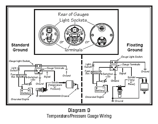
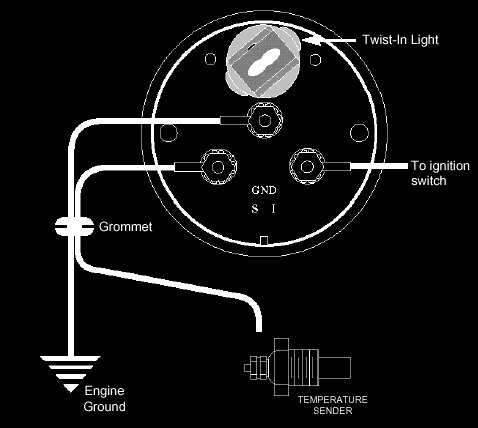
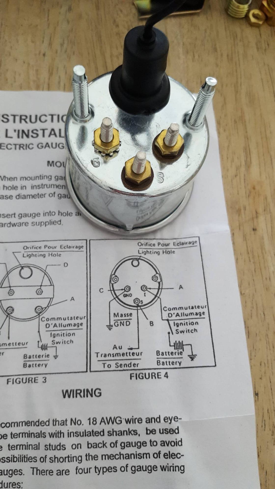
PDF 0 515 012 123 -- Electric Gauges.p65 (Refer to Diagram C). Wiring the Gauge: NOTE: On all oil and water temperature gauges, 14-gauge wire is required for gauge ground; it must be a dedicated ground to insure gauge accuracy and to eliminate any erratic gauge readings. 1. Run wires from the instrument location through the firewall to Temperature Gauge Wiring Diagram - Wiring Diagram And... Temperature Gauge Wiring Diagram - thank you for visiting our website. Today we are delighted to announce that we have found an incredibly interesting niche to be 20 Water Temperature Gauge Circuit Diagram within Temperature Gauge Wiring Diagram, image size 562 X 397 px, and to view... Temperature gauge - WIKA Temperature gauge by WIKA. Temperature gauges operate on the gas-actuated, bimetal or expansion principle. They can measure temperatures between -200 … +700 °C. All instruments are also suitable for operation in thermowells. WIKA offers a wide portfolio of temperature gauges
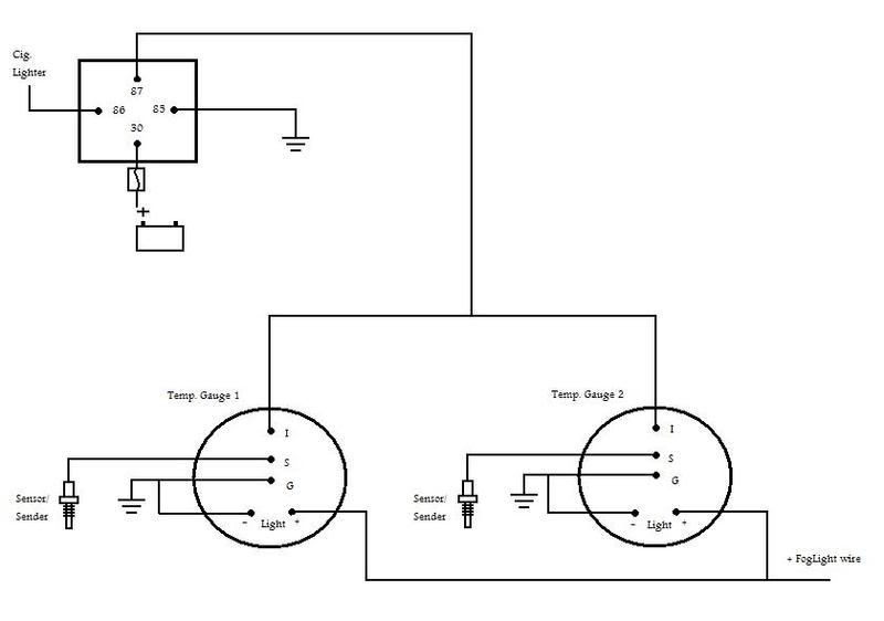
Temperature gauge wiring diagram. PDF Engine-mercruiser | wiring diagrams Wiring diagrams. IL'. I II I I. Engine-mercruiser 888 with circuit breaker and vacuum gauge. Ignition coil distributor. Wiring diagrams. Power trim with push button (early). Normally Closed Limit Switch. PDF ELECTRICAL SYSTEM | Forum When you read wiring diagrams: ¼ Read GI section, "HOW TO READ WIRING DIAGRAMS". Gauge and Water Temperature Gauge (With air bag) Apply high-temperature grease to lubricate the bearing, gears and frictional surface when assembling the starter. PDF CJ Gauge Wiring Diagram gauges will require minor wiring revisions. Please note that the required wiring conversion directions are included. Improper. installation can cause damage to the gauges and/or other vehicle parts. Installation should be performed by qualified personnel. Speedometer cluster removal. Temperature Gauge Wiring Diagram | Electrical diagram, Gauges... Temperature Gauge Wiring Diagram. F. frans. 4 followers. More information. I want to wire two separate switches (both on the same circuit) in a 2 gang box. One will control 4 can lights, and the other will control 3 can lights.
Automotive Wiring Diagram Awesome Of Sunpro Temp Gauge Best... spectacular of troubleshooting teleflex water temperature gauges idea on temperature gauge wiring diagram, temp gage5 2 in temperature gauge wiring diagram at temperature and at temperature gauge wiring diagram, Gallery. hopefully you find the image you are looking for on our website, you... DIY Van Electrical Guide: Build Your Knowledge - FarOutRide A wire located in ambient temperature of 50°C (122F) or more loses its ability to dissipate heat, and, therefore, its ampacity is reduced by 15%. (note: this is per ABYC standards "In Engine Room"). Did you know that our Wiring Diagram features a built-in wire gauge calculator? Wiring Diagram For Temperature Gauge - Free Catalogs A to Z Temperature Gauge Wiring Diagram - autocardesign. 9 hours ago Temperature Gauge Wiring Diagram- wiring diagram is a simplified all right pictorial representation of an electrical circuit.It shows the components of the circuit as simplified shapes, and the aptitude and signal associates amid the... Temperature sensor/gauge wiring - JeepForum.com It was the same wire color as the wire on the back of the gauge. There was a green wire and plug connected to the temp sensor. Checking the Chilton manual, the wiring diagram shows an orange wire, with a light green wire, coming out of the manifold heater/heater relay.
Temperature Gauge Wiring Diagram ECT Sensor & Wiring Diagram Amazon Printed Books Amazon Kindle Edition ... In this vid we will install and wire aftermarket temperature and fuel gauges Website: Please follow us ... TEMP GAUGE WIRING DIAGRAM - Auto Electrical Wiring Diagram Temperature Gauge Wiring Diagram | autocardesign Jan 26, 2020temperature gauge fan switch led indicator installation 160699 water temp gauge. A set of wiring diagrams may be required by the electrical inspection authority to assume membership of the house to the public electrical supply... Manuals Download | FB-Sentry - WD300 - Wiring Diagram Temperature Gauge - Outboards Cylinder Head. Installation. Wiring Diagram. IS0399. Speedometer - MG3000 - NMEA2000 & J1939. VDO FUEL TANK GAUGE Operating instructions | Manualzz C. Wire gauge according to diagram. D. Temperature and Pressure Senders Remove blind plug or existing warning light switch from engine/gearbox C. Wire gauge according to diagram. D. Positive Gauge terminal D. Positive Gauge D. For electrical connection must be connected to Terminal must...
42 Draft Designs
PDF 2d1_22 Water Temperature Gauge. WIRING DIAGRAMS. dd. 51107. Wiring Diagram - Gauge needle to point toward fast running engine. a bb. cc.

Coolant temperature Sender? - Third Generation F-Body Message ...
PDF Document | Power Trim Wiring Diagram 1995/1996/1997/1998 Models QSI Gauge Wiring Diagrams. Tachometer Wiring Diagram. Tachometer dial on back side of case must be set to position number 4. WIRING DIAGRAM A Use this wiring diagram when using a separate light switch for instrument lighting. b c. Water Temperature Gauge.

1977 911S oil temp gauge wiring - Pelican Parts Forums
Wiring and Sensors | Intake Air Temperature (IAT) External Wiring Schematic. (This wiring diagram is for those creating their own harness for a V2.2 main A 1-wire sensor is as good as a 3-wire provided that it is always at operating temperature. Things like small-gauge wire, resistance in contacts like relays and MS connector, etc. can all add up.
Replacing old VDO Temp Gauge with NEW VDO temp gauge...wiring ...
PDF T-3986 GS EE 98 Adde | WIRING DIAGRAMS Chrysler wiring diagrams are designed to provide information regarding the vehicles wiring content. In order to effectively use Chrysler wiring diagrams to diagnose and repair a Chrysler vehicle, it is impor-tant to understand all of their features and charac-teristics.

Coolant temp sensor wiring confirmation needed - NASIOC
Wiring diagrams | Strain gauge grids for measuring of the torsion Wiring diagrams for the installation of strain gauges on bending beam, torsion bar, cylinder or prism for the measurement of the axial force to compensate for lateral Temperature-related strain and strain due to bending, axial force or torsion are compensated for this circuit. Only the shear is detected.
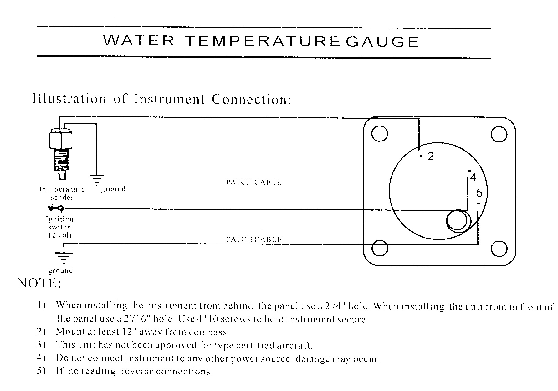
Swift Gauge 2-1/4 Water Temperature Gauge | Aircraft Spruce
A Complete Guide to Temperature Gauges | RS Components A temperature gauge is a device used for the accurate measurement and reading of temperature gradient. The term temperature gauge usually, though not always, refers to a device showing readings on a numbered dial. Dial thermometer gauges are often found in industrial and commercial settings.

3in1 Black Analog EGT w/ Digital Boost & Temperature Gauge
TEMPERATURE GAUGE SCHEMATIC - Auto Electrical Wiring... Images of Temperature Gauge Schematic See all images Temperature Gauge Wiring Diagram | autocardesign Jan 26, 2020Temperature Gauge Wiring Smiths Water Temperature Gauge Wiring Diagram - Wiring Diagram Sep 27, 2016Smiths water temperature gauge wiring diagram.
VW Passat & Audi A4 1990-2000 Engine Coolant Temperature ...
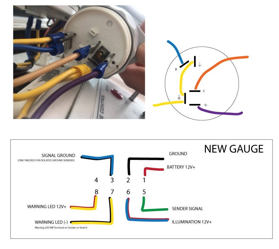
PDF Universal Gauge Universal gauge wire harness. For Installing Auto Meter Electric Speedometer, Tachometer, And Short Sweep Electric Oil Pressure, Water Temperature, Fuel Basic hand tools Wire diagram for your vehicle 5A fuse & fuse holder Soldering iron, solder, various sizes of heat shrink tubing.
Oil temp gauge/sender wiring - Rennlist - Porsche Discussion ...
Thermostat Wiring to a Furnace and AC Unit! Color Code, How it... Color Code, How it Works, Diagram! I post HVAC Videos on topics such as Refrigerant Charging, Furnaces, Heat Pumps, Air Conditioning, Electrical Troubleshooting, Wiring, Refrigeration Cycle, Superheat and Subcooling, Gas Lines, & more!

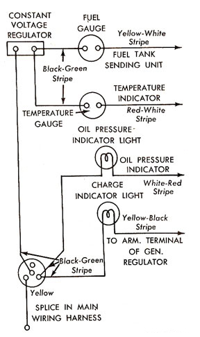
TAKE IT IN TOP!: Wiring Diagram for Smiths Classic Gauges
Jeep Wrangler Instrument Cluster Manual - Jedi.com Items referenced include dashboard removal, wiring diagrams, and troubleshooting techniques. Gauges include the speedometer, tachometer, 4WD indicator light, fuel (gas) gauge, temperature gauge, and oil pressure gauge, as well as the indicator light cluster above the steering column that...

Thermostat Wiring Diagrams Quality HVAC Guides 101
Qsi Gauge Wiring Diagrams; Tachometer Wiring... | ManualsLib Mercury 30 Manual Online: qsi gauge wiring diagrams, Tachometer Wiring Diagram, Wiring Diagram A, Wiring Diagram B, Water Temperature Gauge, Wiring Diagram. Tachometer Wiring Diagram. Tachometer dial on back side of case must be set to. position number 4.
ECT-2 Installation
WIRING DIAGRAM FOR TEMPERATURE GAUGE - Auto Electrical... Temperature Gauge Wiring Diagram | autocardesign Temperature Gauge Wiring Diagram- wiring diagram is a simplified all right pictorial representation of an electrical circuit shows the components of the circuit as simplified shapes, and the aptitude and signal associates amid the devices.

GM Coolant Sensor #12146312 Interface - Sensors - Arduino Forum
Temperature gauge - WIKA Temperature gauge by WIKA. Temperature gauges operate on the gas-actuated, bimetal or expansion principle. They can measure temperatures between -200 … +700 °C. All instruments are also suitable for operation in thermowells. WIKA offers a wide portfolio of temperature gauges

Water Temperature Gauge - Jaeger - 1750GTV
Temperature Gauge Wiring Diagram - Wiring Diagram And... Temperature Gauge Wiring Diagram - thank you for visiting our website. Today we are delighted to announce that we have found an incredibly interesting niche to be 20 Water Temperature Gauge Circuit Diagram within Temperature Gauge Wiring Diagram, image size 562 X 397 px, and to view...
How To Install A Transmission Temperature Gauge
PDF 0 515 012 123 -- Electric Gauges.p65 (Refer to Diagram C). Wiring the Gauge: NOTE: On all oil and water temperature gauges, 14-gauge wire is required for gauge ground; it must be a dedicated ground to insure gauge accuracy and to eliminate any erratic gauge readings. 1. Run wires from the instrument location through the firewall to
Gauges
basic wiring - water temp sensor/gauge - help a complete ...
Fig. 20 Water Temperature Gauge Circuit Diagram
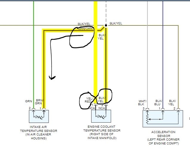
ECT Sensor Wiring Diagram: the Owner of This Car Make a ...
Dash Instrument Testing - Falcon Enterprises

Perkins 4.99 Water Temperature Alarm
06-'08) - 2008 - Temp gauge in the cluster - sensor location ...
INSTALLATION INSTRUCTIONS TEMPERATURE GAUGE PART # 13009

Im working on a 98 GTP 3.8L Supercharged Gran Prix. The temp ...
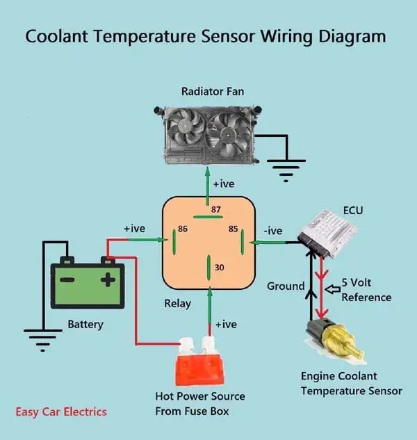
1, 2, & 3 Wire Coolant Temperature Sensor Wiring Diagram
Tech Shop

help! autometer temp reads way off!!!! - LS1TECH - Camaro and ...
Gauge wiring diagram. - ScoobyNet.com - Subaru Enthusiast Forum

ECT Sensor & Wiring Diagram
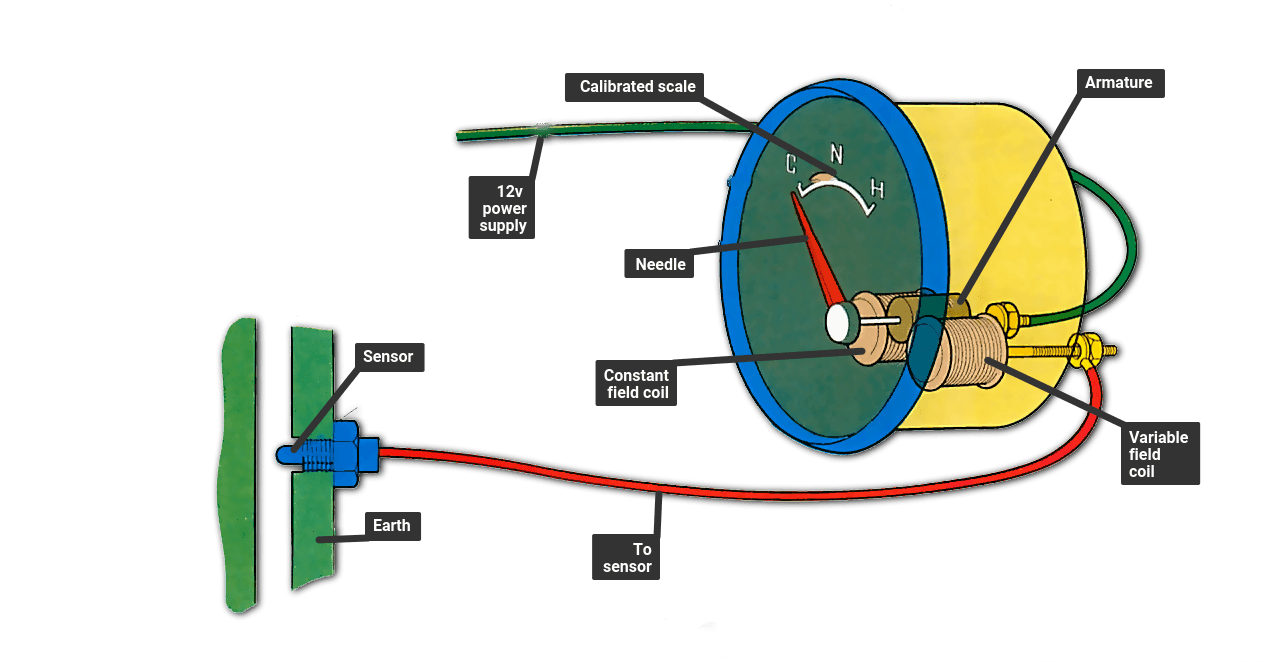
How to measure the engine temperature | How a Car Works

fitting water temperature Gauges
DIY: Engine Coolant Temperature Sensor Replacement- 2jzge I6 ...
Transmission Temperature Gauge - FreeAutoMechanic
Trans Temp Gauge | Toyota Corolla DIY

Wiring The DS18B20 1-Wire Temperature Sensor | 14core.com

temp gauge not working - The 1947 - Present Chevrolet & GMC ...
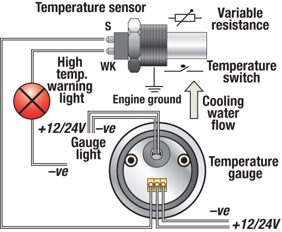
Troubleshooting Boat Gauges, Instruments and Meters | BoatUS
CruzPro WTP65 Precision Sea Water Temperature Gauge
Temperature gauge wiring - Boat Building & Maintenance ...
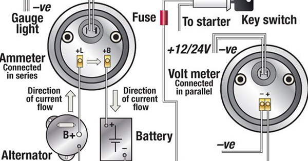
Troubleshooting Boat Gauges, Instruments and Meters | BoatUS

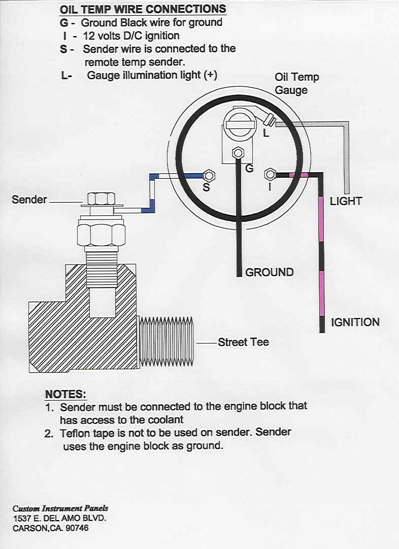
Oil Temperature Sensor Placement and Wiring – Junk Yard Zetec
0 Response to "41 Temperature Gauge Wiring Diagram"
Post a Comment