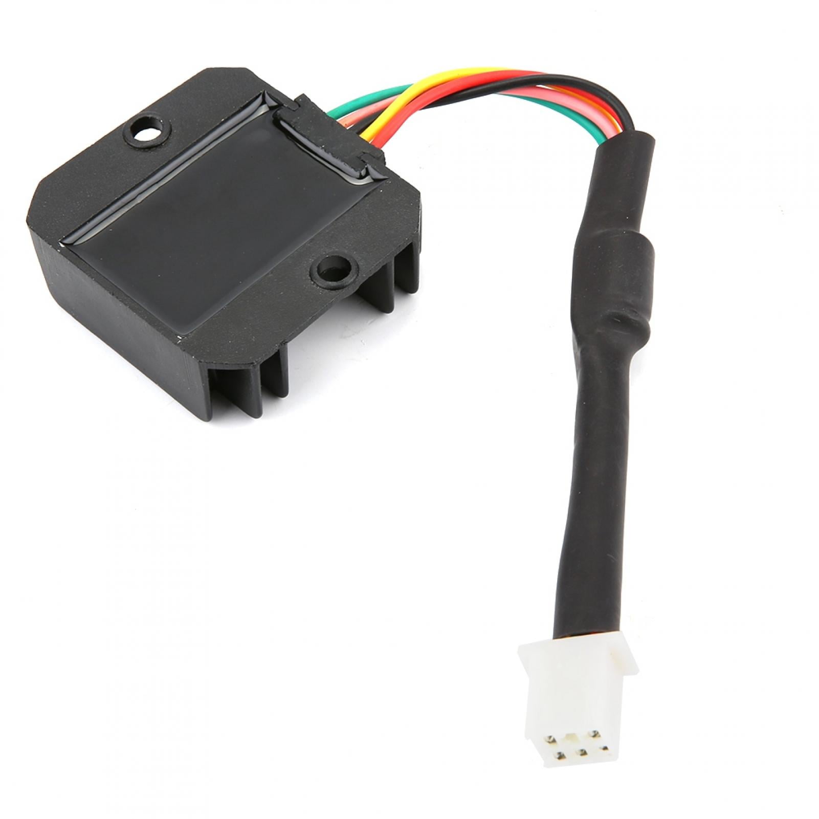
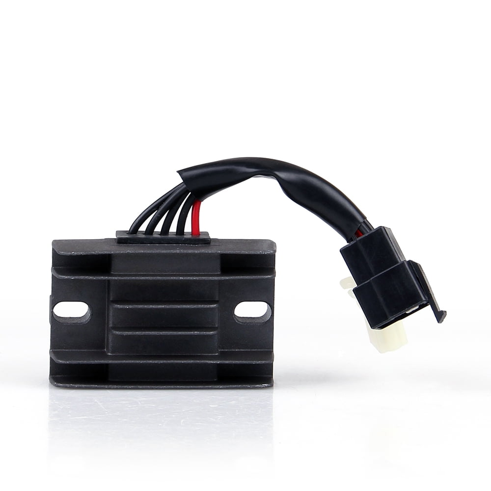
44 5 wire regulator rectifier wiring diagram
5 pin regulator rectifiier wiring diagram Sana makatulong po ito sainyo mga bro. Para sa iba pang vidio wag nyo pong kalimutan ... Paano ang connection pag nag convert ka ng 4 wires regulator rectifier sa sa 5 wires regulator rectifier. Can a 6 wire rectifier be put on a bike with a 5 wire rectifier. ... but looking closely at the circuit diagram the green and reds both merge into a single wire shortly after the connector. ... I have to say when I fitted a Honda regulator on my GS550 I had an extra wire that had to be connected to a switched live (I used the feed to the ...
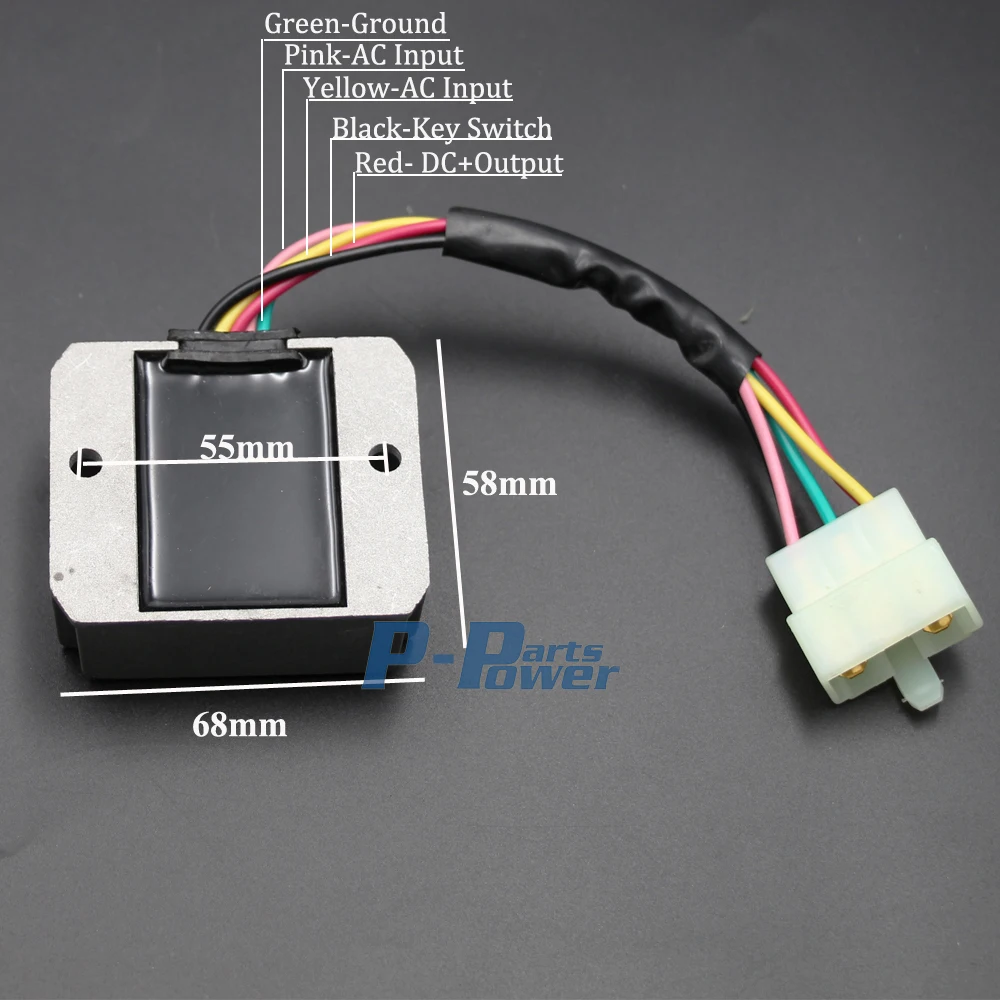
RECTIFIER REGULATOR 5-PIN/ DIFFERENCE COLORS 4 Wire Regulator wiring diagram and connection/Rectifier Voltages tutorial (philippines)(Asia).

5 wire regulator rectifier wiring diagram
5 pin regulator rectifiier wiring diagramSana makatulong po ito sainyo mga bro.Para sa iba pang vidio wag nyo pong kalimutan magSUBSCRIBELIKE AND SHARETO GOD... 4-PIN 5-PIN RECTIFIER DIFFERENCE CONNECTIONS. BARAKO 2, 4 pin DC CDI, naka 5 pin full wave rectifier regulator wiring diagram tutorial..Подробнее. 5 to 4 wire or 4 to 5 wire connection sa Rectifier Regulator ng motorПодробнее. Motorcycle Regulator Diagram and Amazon: Wires V Voltage Regulator Rectifier - 18+ Motorcycle Regulator Diagram - Wiringg.net. Motorcycle Regulator Diagram and ...
5 wire regulator rectifier wiring diagram. Jan 19, 2022 · 5 Wire Regulator Rectifier Wiring Diagram– One of the most difficult automotive fix tasks that a mechanic or repair shop can consent is the wiring, or rewiring of a car’s electrical system. The pain really is that all car is different. in the manner of grating to remove, replace or repair the wiring in an automobile, having an accurate and detailed 5 wire regulator rectifier wiring diagram is vital to the exploit of the repair job. Buy Voltage Regulator 5 Wires 12V Rectifier Motorcycle Compatible with Dirt Bike ATV GY6 50 150cc Scooter Moped JCL NST TAOTAO: Rectifiers - Amazon.com ... Rectifier Regulator Wiring Diagram – 12v rectifier regulator wiring diagram, atv regulator rectifier wiring diagram, honda regulator rectifier wiring diagram, Every electric structure consists of various distinct components. Each part should be placed and linked to different parts in particular way. Otherwise, the arrangement will not work as it ought to be. I just downloaded the wiring diagram for the "GT" version and that shows a wiring paradigm much closer to what I was expecting; all 3 alternator wires are headed for the regulator/rectifier. On the "GN" wiring diagram they show the green with white trace wire headed for the light switch (that don't...
If the engine earth wire was missing the engine would run but you may have problems with the CDI unit failing because the electrical system may try to * This diagram shows the later 50cc and 80cc two stroke wiring using an eight pin connector on the rectifier / regulator. Refer to the separate diagram... Rectifier Regulator Wiring Diagram - easywiring May 15, 2021Regulator rectifier diagram here you are at our site this is images about regulator rectifier diagram posted by maria nieto in wiring category on may 08 2019. Provided below is an online pdf document for lamberts bikes 3 phase 6... WIRING DIAGRAM. Components A6 CDI controller B1 Throttle position sensor B3 Wheel speed sensor E6 Thermoswitch (EXC-F SIX DAYS) G1 Battery G2 Generator H1 Right rear flasher H2 Left front flasher H3 Left rear flasher H4 Right front flasher H5 Brake/tail light H7 Parking light H9 License plate... I have a 5 wire reg/rec 3 yellow go to stator , red wire goes to the starter relay, black/white wire was originally wired as a ground.
Mercury 75 Manual Online: 75/90 Wiring Diagram (1-2-3 Firing Order). BLK BLACK BLU BLUE BRN BROWN GRY GRAY GRN GREEN PUR PURPLE RED RED TAN TAN VIO VIOLET WHT WHITE YEL YELLOW q p o a - Stator b - Trigger c l - Enrichment Valve. m - Voltage Regulator/Rectifier. Oct 02, 2021 · Wiring diagram for voltage regulator. However this diagram is a simplified version of this arrangement. Here is a wiring diagram of the typical 5-wire CDI system on a lot of scooters comprising pick-up input battery 12 volts in Gnd and Ignition coil out pins. Marvellous Motorcycle Regulator Rectifier Wiring Diagram Ideas size. Jul 28, 2021 · 5 Pin Rectifier Wiring Diagram. by Vallery Masson on July 28, 2021. July 28, 2021 on 5 Pin Rectifier Wiring Diagram. For example on a 1981 kawasaki kz440 there are 5 wires going to the oe part. Alternatively you can plug the connector onto the 4 pins row and leave the s gnd wire unconnected. Yamaha Rs 4 Engine Diagram Download In 2020 Motorcycle Wiring Electrical Diagram Electrical Wiring Diagram. ...wire pressing on a crystal of galena (lead sulfide) to serve as a point-contact rectifier or "crystal A more efficient alternative to a shunt voltage regulator is an active voltage regulator circuit. An active regulator employs reactive components to store and discharge energy, so that most or all current...
Amazon.com: Voltage Regulator 5 Wires 12V Rectifier ...
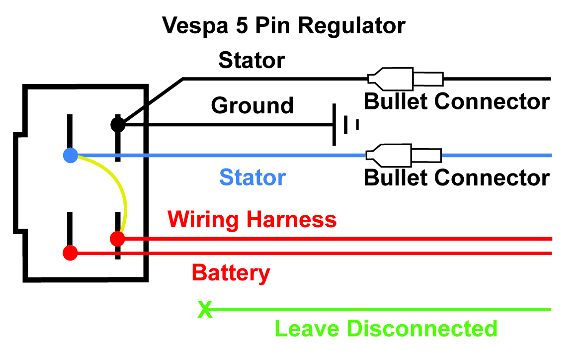
Diagram 2: Simply plug the connector onto the 5-pins row, and make sure that the pin assignments and wire assignments are matched correctly. Most bikes have a stator that produces AC voltage powered by magnet in the flywheel, this then goes into a rectifier\regulator, which converts to DC and...

Buy Voltage Regulator Rectifier Fits for Mercury Marine ...
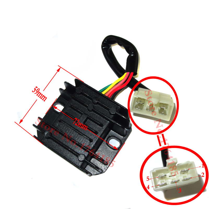
2 phase 5 wire motorcycle regulator rectifier wiring diagram pdf. We ve even included standard wire colours where appropriate. Lamberts bikes motorcycle part wiring diagrams. Simply plug the connector onto the 5 pins row and make sure that the pin assignments and wire assignments are matched correctly. M 3 2 2 2 phase 5 wire.
LYUMO Voltage Regulator Rectifier, Voltage Rectifier ...
5 pin regulator rectifiier wiring diagram Sana makatulong po ito sainyo mga bro. Para sa iba pang vidio wag nyo pong kalimutan ... Rectifier Regulator 5ipn Installation Manual & Diagram Manual installation Rectifier Regulator 5Wires Deffernce Colors wires Step ...
Mad Hornets Regulator Rectifier Voltage Fit For Suzuki GN125 250cc 5 wires
Mar 5, 2021 — Why would you need the regulator-rectifier to *also* be on the same ... The other four-wire regulators I've seen have two wires for AC input ...
Regulator Rectifier 12 Volt 5 Pole AC/DC VSX VLX PX Stella
The regulator/rectifier prevents the battery from being over charged. NOTE: The AC Only, DC Only, Dual Circuit, Tri-Circuit as well as the 5 and 10 amp To do this, a wiring diagram for the equipment is essential. The original keyswitch may also create a challenge. Even though the keyswitch harness...
Magneto/Regulator Wiring for 2 to 4 stroke swap | Pocketbike ...
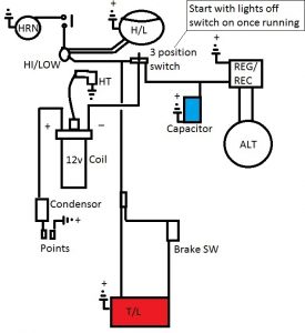
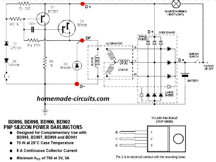
Understanding wiring of motorcycle voltage regulators. Motorcycles are usually equipped with permanent magnet AC generators. In this system, both the ends of the winding go to the Rectifier section which converts AC to DC voltage and then the Regulator section regulates to...

Buying Guide | 893640T01 5 Wires Voltage Regulator Rectifier ...
5 pin regulator rectifiier wiring diagram Sana makatulong po ito sainyo mga bro. Para sa iba pang vidio wag nyo pong kalimutan ... In this episode Alan and Alec discuss Regulator Rectifiers, what they are, what they do, why you need one, and which one do you ...
Price history & Review on GY6 50 150cc Scooter Voltage ...
Wiring Diagrams. This diagram shows how to check the rectifier/regulator unit on H2 or H1E/H1F models with a voltmeter and an ammeter.

Voltage Regulator - 5 Wire / 1 Plug for GY6 150cc 200cc 250cc ...
Wiring a Chinese ATV from start to finish with an All New Wiring Harness! Chinese quad/scooter rectifier/regulator teardown with schematic. bigclivedotcom.

5 WIRE 2 Phase Motorcycle Regulator Rectifier 12V DC Bridge ...
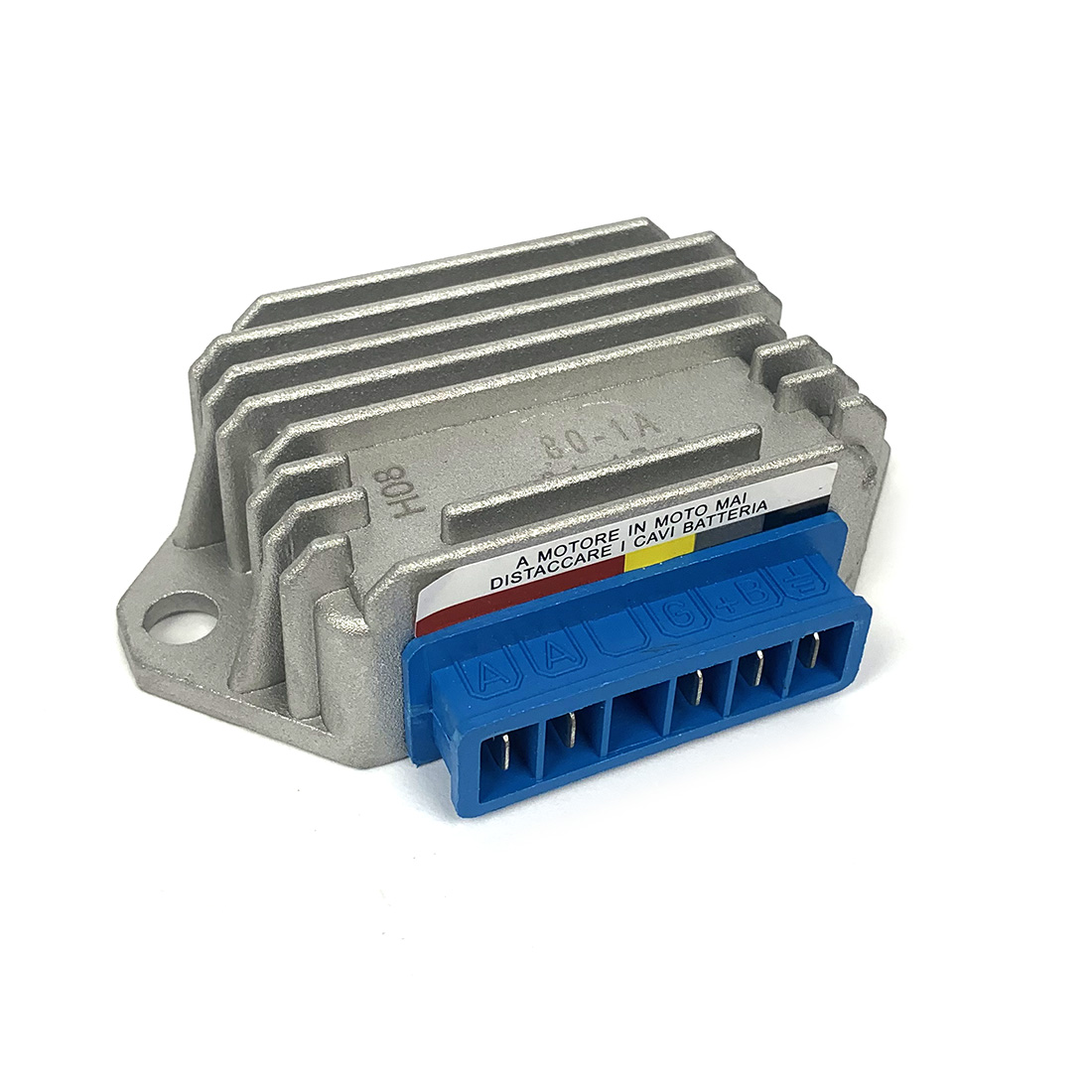
Rectifier regulator wiring diagram for honda motorcycle 6. B+ regulator rectifier & regulator * this diagram shows the early 50cc and 80cc two stroke wiring using a five pin connector on * eight pin rectifier / regulator incorporates the indicator relay and oil light check function.

ATV GY6 50 150cc Scooter 4 Wires Voltage Regulator Rectifier Motorcycle Boat
Wiring a Rectifier/Regulator? Thread starter AnvilBlockForge. Light bulbs with filaments can run on AC or DC. LED lights need DC. A rectifier and capacitor just changes AC to DC. A regulator keeps the DC output voltage steady so that it doesn't increase with RPM.

Wiring this regulator? | Mini Dirt Bikes & Pit Bikes Forum
Regulator/Rectifier unit for the SOHC Honda CB650 four. (Will not mount up to the DOHC models Click here for a diagram to see how this unit would wire into your bike. This unit requires a plugs into the original regulator and rectifier connectors on the wiring harness but requires custom mounting.
Recitifer Regulator Signal Wires – Rick's Motorsport ...
Yamaha Rectifier Wiring - Wiring Diagram Schemas from images-na.ssl-images-amazon.com. From the 78xx voltage regulator integrated circuit series, 7806 ic is used to regulate the output voltage please i need information/circuit diagram on fire detection and fire suppression systems in an aircraft.

Buy Universal Voltage Regulator Rectifier, Electrical Voltage ...
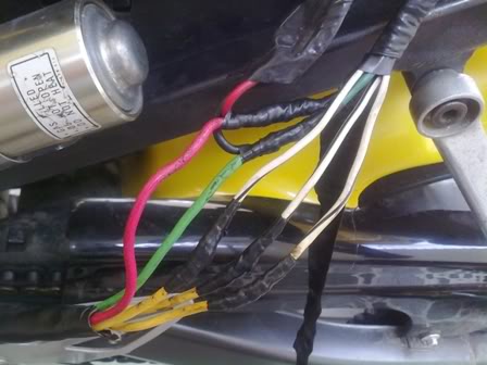
5 pin regulator rectifiier wiring diagram Sana makatulong po ito sainyo mga bro. Para sa iba pang vidio wag nyo pong kalimutan ... Paano ang connection pag nag convert ka ng 4 wires regulator rectifier sa sa 5 wires regulator rectifier.

#37 | 4 Wires to 5 Wires Regulator rectifier | Paano ang connection (wiring diagram)
Print the electrical wiring diagram off and use highlighters to be able to trace the routine. When you make use of your finger or perhaps stick to the circuit together with your eyes, it's easy to mistrace the circuit. 1 trick that I actually 2 to printing exactly the same wiring plan off twice.

Universal 4 Wire 2 Phase Motorcycle Regulator Rectifier 12V Quad Bike Scooter-buy at a low prices on Joom e-commerce platform
3 wire rectifier regulator wiring diagram. First we wire each subwoofer in a series and. 3 wire rectifier regulator wiring diagram. Honda engines gx630r qzb3 engine jpn vin gcbek. As no starter is used in the case of electronic ballast application, the wiring diagram is slightly different.
Motogadget M-Unit & Ricks Regulator/Rectifier Help | Cafe ...
The wiring diagrams show the type of keyswitch that is compatible with the alternator system shown. 7. Typical Dual Circuit Alternator Wiring Diagram. Alternator AC output. Wire regulator rectifier. DC Output wire. Anti-afterfire solenoid.

Universal regulator rectifier
Aug 28, 2021 · Vacuum Diagram As Well 2001 Ford F 150 5 4 Vacuum Line Diagrams On size. 5 pin rectifier wiring diagram. On the solder side of. Reddit gives you the best of the internet in one place. Design a regulated DC power supply of 5V which can be used to run a LED using AC voltage as the input.

Voltage Regulator / rectifier units
VFR TECH. Modifications. Producing A Fix For The Regulator/rectifier Wiring Issue. I checked the wiring diagram to be sure there wasn't something designed to make the reading low on purpose….nothing. As a test I jumpered a wire from the positive terminal to the sensor wire…bingo...
Recitifer Regulator Signal Wires – Rick's Motorsport ...
Mar 7, 2016 — The 7-wire rec/reg is likely for the original energized rotor type alternator. 2 of its wires control power to the rotor, which regulates output ...

37 | 4 Wires to 5 Wires Regulator rectifier | Paano ang ...
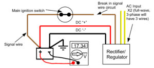
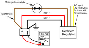
Mar 29, 2017 — To illustrate, here's a diagram showing a full-wave Rectifier/Regulator with a signal wire operating properly: The battery in this circuit is ...

Tuzliufi Voltage Regulator Rectifier Compatible with Mercury 194-3072K1 854515T2 883071T1 883072T1 883072T2 893640-002 6 Wires 25 30 40 50 60 hp 135hp ...
This is about replacing the standard equipment Regulator/Rectifier with a more efficient component. You can do this in event of failure rather than replace with Ask on the forum for your particular model which one you should check if in doubt. Next, examine the wires and connectors between the stator...
Regulator Rectifier Voltage Fit Honda CH125CC-250CC 5 wires | eBay
5 pin regulator rectifiier wiring diagram Sana makatulong po ito sainyo mga bro. Regulator Connection 3 speed 4 wire cooler motor and 3 step switch Tools buy link Amazon Paano ang connection pag nag convert ka ng 4 wires regulator rectifier sa sa 5 wires regulator rectifier.

Regulator-Rectifier Tester
Jul 1, 2016 — CAUTION. Installation of electrical devices can be hazardous. Connecting wires incorrectly can result in severe damage. Always.

Tuzliufi Voltage Regulator Rectifier for Outboard 5 Wires ...
Photosensitive Cell. Full Wave Rectifier. WIRING DIAGRAM A wiring diagram shows, as closely as possible, the actual location of all component parts of the device. Wiring Diagram. This symbol denotes the coil function, provided by a solid-state control module, 30 VA transformer, two fuses in the...
Regulator /Rectifier and some wiring -
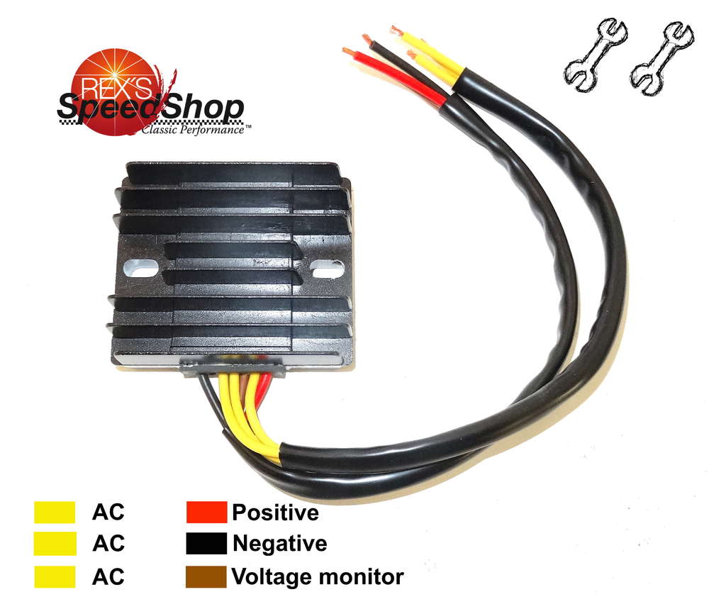
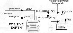
5 wire regulator rectifier wiring diagram. May 11 2018 wiring diagram. Wiring diagram for voltage regulator. 2 yellow wires ac inputs white red dc output black yellow dc output and a brown wire. How to wire the 5 cables not in a row. The yellows all come from the alternator you can connect these in any order to each other the red wire from the ...
Regulator/rectifier info | Kawasaki Motorcycle Forums
REGULATOR/RECTIFIER 7003-RR150 Tech Support: 360-687-4530 REGULATOR/RECTIFIER tech_support@trailtech.net WIRING GUIDE WIRING FOR SMALL BATTERIES UNDER 4 Ah: Trail Tech Regulator/Rectifier 7003-RR150 2 Yellow Wires: Red Wire: Blue Wire: Black Wire: Lighting leads. Connect to lighting leads from stator. Trail Tech stators have yellow lighting leads.
Voltage Regulator Rectifier 5 Wires 5 Pin 12V GY6 Scooter ATV ...
Oil light timer rectifier regulator & regulator. * This diagram shows the later 50cc and 80cc two stroke wiring using an eight pin connector on the rectifier ‰ Three Yellow wires: Three phases of generator, all feed directly to the rectifier / regulator. ‰ Green wire: Ignition pick up.

Mercury Mariner Outboard Force Voltage Regulator Rectifier ...
Home Theater Component Wiring Diagrams. The diagram here shows how a basic 4-wire thermostat is connected as indicated by the color code chart below. The basic Heat + A/C System thermostat typically utilizes only 5 terminals.
Regulator / Rectifier Wiring - CBR Forum - Enthusiast forums ...
Motorcycle Regulator Diagram and Amazon: Wires V Voltage Regulator Rectifier - 18+ Motorcycle Regulator Diagram - Wiringg.net. Motorcycle Regulator Diagram and ...

Stator - 4 wire vs 5 wire compatability | X-H2o
4-PIN 5-PIN RECTIFIER DIFFERENCE CONNECTIONS. BARAKO 2, 4 pin DC CDI, naka 5 pin full wave rectifier regulator wiring diagram tutorial..Подробнее. 5 to 4 wire or 4 to 5 wire connection sa Rectifier Regulator ng motorПодробнее.
Wiring Solid state Single phase Regulators | JRC Engineering ...
5 pin regulator rectifiier wiring diagramSana makatulong po ito sainyo mga bro.Para sa iba pang vidio wag nyo pong kalimutan magSUBSCRIBELIKE AND SHARETO GOD...

Buying Guide | Rectifier 4 Wires Voltage Regulator ...
6 Wire Universal 12 Volt Regulator Rectifier

Motorcycle Regulator Rectifiers 5 Wires Plug for Yamaha ...
Wiring new rectifier to Indiana 650. 6 wires stock, can I use ...

12 VOLT REGULATOR RECTIFIER COMBINATION UNIT (214W) (S1070)

Voltage Regulator - 4 Wire / 1 Plug for Dirt Bikes Scooters ...
Regulator Wiring Diagrams

DC Regulator Rectifier, 150 watt Full Wave with Relay | TrailTech
Wiring Solid state Single phase Regulators | JRC Engineering ...

Regulator/ Rectifier, (DC) (unwired)

GY6 150cc 11 Pole Regulator Rectifier 5 Wire
Understanding Motorcycle Voltage Regulator Wiring - Homemade ...
0 Response to "44 5 wire regulator rectifier wiring diagram"
Post a Comment