45 free body diagram for pulley
What would the free-body diagram of the balance of forces be for a rope and a pulley: a. For the rope turned 90 degrees? b. For the rope turned 180 degrees? 3. Experiment! Strings, Tension and Pulleys An ideal pulley is one that simply changes the direction of the tension. A man is holding a box at a constant height off the ground by means of a ... Download scientific diagram | (a) A two-pulley belt drive. (b) Free body diagrams of the belt on the driver and driven pulleys from publication: Microslip friction in flat belt drives | The ...
2.55 With reference to Figure P2.55 (a) Draw a free-body diagram of the structure supporting the pulley. (b) Draw shear and bending moment diagrams for both the vertical and horizontal portions of the structure. 48 in. -12 in Cable 27 in. 100 lb Cable 12-in. pulley radius 100 lb FIGURE P2.55
Free body diagram for pulley
The pulley is a solid disk with a mass of 1.25 kg and an unknown radius. The rope passes over the pulley on the outer edge. What is the acceleration of the blocks? As usual, the first place to start is with a free-body diagram of each block and the pulley. Remember that a free-body diagram must only include the external forces acting on the body of ... A light rope is attached to it and runs over a pulley.Definition of weight, vector form: →w=m→gw...Definition of weight, scalar form: w=mgw=mgNewton’s second law, vector form: →Fnet=∑...Newton’s second law, component form: ∑→Fx... Using the pulley system illustrated to the right below as an example, the basic method for discussed. As in Lessons 15, 16 and 17, the basic method is to draw a free body diagram of the forces involved, write an expression for the net force, and then solve for the acceleration. In a pulley system two masses are strung over a pulley. Note that ...
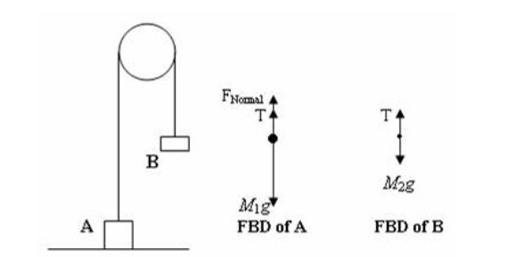
Free body diagram for pulley. Free-Body Diagrams Instructions When analyzing problems that involve forces, it is convenient to draw a diagram where all of the forces acting on a body are drawn as vectors. This diagram creates a simplified sketch of the body as an isolated "particle" or " free-body " in space. As long as the body is expected only to move linearly (translationally), the size of the actual body is ... A free body diagram shows all of the forces acting on an object, even if their effects are balanced out by another force. We will use free body diagrams to consider different situations involving the lamp that you find at your lab station (Figure 3.1 ). One force that always acts on the lamp is gravity. The Free Body Diagram Interactive is shown in the iFrame below. There is a small hot spot in the top-left corner. Clicking/tapping the hot spot opens Why not try our Tutorial Video on Drawing Free-Body Diagrams. In 10 minutes, you will learn what a free-body diagram is, how to recognize force types... placed over a pulley as indicated in the diagram below. There are TWO free-body diagrams since there are two masses in this problem. M 1 M 2 Pulley X Y W 1 T 1 W 2 T 2 Free-Body Diagram for M 1 Free-Body Diagram for M 2 i) W 1 is the force of gravity on mass M 1 and W 2 is the force of gravity on mass M 2. W 1 = M 1 g and W 2 =M 2 g. ii) T 1 is ...
In a Free-Body Diagram, the object is represented by its expression, usually a line, box, or a dot. The force vectors that act upon the object are represented by a straight arrow while moments are represented by a curved arrow around their respective axis as shown in the image below where a force is acting at B and a moment acts around A. Use the free body diagram of the pulley (Figure 4) to answer the Pre-Lab Questions. 1. Draw a free body diagram for M1. 2. Draw a free body diagram for M2. 3. Apply Newton's 2nd Law to write the equations for M1 and M2. You should get two equations with Tension in the string, weight for each mass and accelerations for each mass (a1 and a2). 4. Jul 08, 2021 · Pulley problems for IIT JEE and JEE Main - Excellent way to practice free body diagrams and master application of newtons second law of motion. Free-Body Diagram Example Problem 3 Bank robbers have pushed a 1000 [kg] safe to a second-story floor-to-ceiling window. They plan to break the window, then lower the safe 4.0 [m] to their truck. Not being too clever, they stack up 600 [kg] of furniture, tie the rope between the safe and the furniture, and place the rope over a pulley.
The free body diagram helps you understand and solve static and dynamic problem involving forces. It is a diagram including all forces acting on a given object without the other object in the system. You need to first understand all the forces acting on the object and then represent these force by arrows in the direction of the force to be drawn. Coordinate systems and Common acceleration - Pulley in Physics. For an ideal pulley, the tension is the same throughout the rope (therefore the same symbol T in both diagrams). This is generally a common consideration for pulley tension problems. The acceleration a of each subject is indicated. The cart accelerates to the right when the ... The solution here will use the approach of a free-body diagram and Newton's second law analysis of each individual mass. The free-body diagrams for the two objects are shown below. Because the parallel component of gravity on m 1 exceeds the sum of the force of gravity on m 2 and the force of friction, the mass on the inclined plane (m 1 ) will ... Pulleys and Tension ProblemSum of Forces in Inclined Frames of ReferencePulleys, Tension, and Extension SpringsForces Subscripts ConvectionTwo-Force Members...
Forces and Newton's Laws of Motion
Making accurate free body diagrams for a system of blocks connected by string and pulleys is an important step towards writing the correct equations of motio...

Free Body Diagram (how do you make free body diagrams?) #6
Apr 13, 2017 — The same principle applies to pulleys. If the pulley is light enough to be considered "massless", then any rotational acceleration of the pulley would ...1 answer · Top answer: Is there any difference between the free body diagram of fixed pulley and movable pulley? Not particularly. The main thing is that you can assume the ...Determining tension and free body diagrams for a three-stage ...Sep 22, 2017Why do the the Normal force of rope on to pulley is not ...Jul 19, 2020More results from physics.stackexchange.com

The beam and the cable (with a frictionless pulley at D ...
Find: Draw the free-body and kinetic diagrams of the crate. Plan: 1) Define an inertial coordinate system. 2) Draw the crate’s free-body diagram, showing all external forces applied to the crate in the proper directions. 3) Draw the crate’s kinetic diagram, showing the inertial force vector ma in the proper direction.

FORCE AND FREE-BODY DIAGRAMS PHYSICS Force - The ...
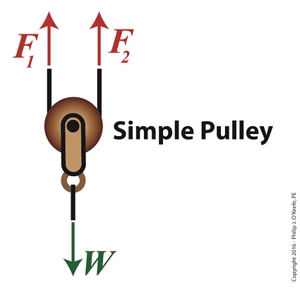
Free body diagrams. The mechanical advantage of a pulley system can be analysed using free body diagrams which balance the tension force in the rope with the force of gravity on the load. In an ideal system, the massless and frictionless pulleys do not dissipate energy and allow for a change of direction of a rope that does not stretch or wear.

Tension, String, Forces Problems with Solutions
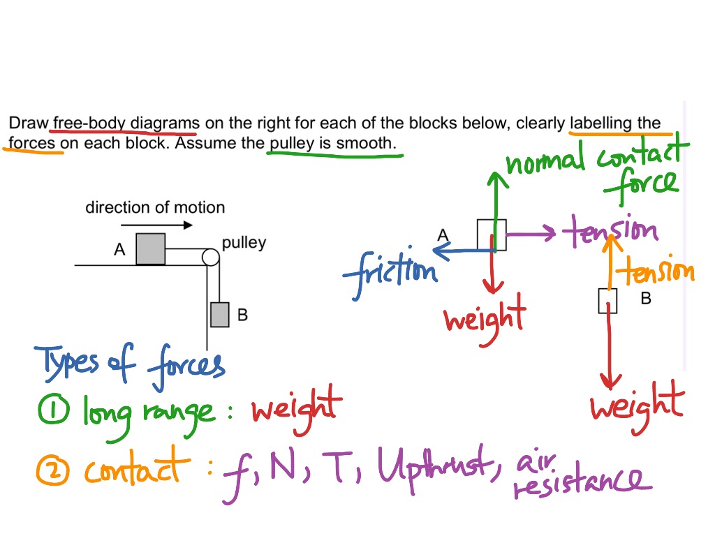
Figure 5.32 (a) The free-body diagram for isolated object A. (b) The free-body diagram for isolated object B. Comparing the two drawings, we see that friction acts in the opposite direction in the two figures. Because object A experiences a force that tends to pull it to the right, friction must act to the left. Because object B experiences a component of its weight that pulls it to the …
Pulley, Table, Ramp Free body Diagrams
3 Wire Alternator Wiring Diagram Source: www.carparts.com. This is a three-wire alternating wiring diagram showing the connections between the different components of a circuit. The circuit comprises three main wires: battery positive cable, voltage sensing wire, and ignition wire. The ignition input wire is attached to the engine.

FORCES AND FREE BODY DIAGRAMS - ppt download
Figure 5.6: A diagram for the system of two objects and a pulley. Figure 5.7: Free-body diagrams if there is no friction. (a) The free-body diagram of the red box. (b) An appropriate coordinate system for the red box. (c) The free-body diagram of the red box, with force components aligned with the coordinate system. (d) and (e), a

Answered: +x Dual pulley Motor 10.600 m 20.200m… | bartleby
free-body-diagrams. T From the above discussions, we have the three equations: This is less than that in case 1 as we predicted. 9. Atwood's machine. Atwood's machine involves one pulley, and two objects connected by a string that passes over the pulley. In general, the two objects have different masses. a a. 10. Re-analyzing the Atwood's ...

(3/8) Simple FBD with Pulley
Step 2 - Draw a free-body diagram of the pulley. A complete free-body diagram of the pulley, shown in Figure 11.3 (a), reflects that fact that the center-of-mass of the pulley remains at rest, so the net force must be zero. There is still a non-zero net torque, about an axis through the center of the pulley and perpendicular to the page,

Free-body diagram of the pulley and the associated vector ...
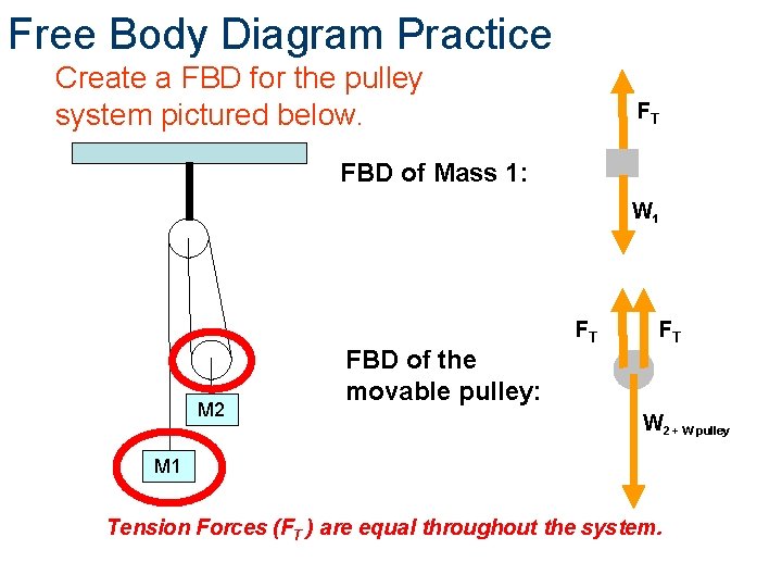
Free Body Diagram Practice M1 M2 FBD of Mass 1: F T FBD of the movable pulley: W 1 W 2 + W pulley F T F T Tension Forces (F T ) are equal throughout the system. Create a FBD for the pulley system pictured below.

Two masses hanging from a pulley (video) | Khan Academy
To further test your understanding of free-body diagrams, see our force problems, which include problems where you need to draw free-body diagrams of objects that move up an incline, hang from ropes attached to the ceiling, and hang from ropes that run over pulleys. For each problem, we provide a step-by-step guide on how to solve it.

Pulley and Cables Free Body Diagram in 2 Minutes! (Example)
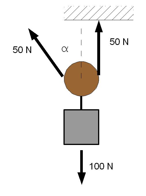
(the pulley is ! assumed massless); string . B. pulls down on the pulley on each side with a force, T, P , ! which has magnitude . T. B. String . A. holds the pulley up with a force . T, P . with the magnitude . T. A. equal to the tension in string . A. The free-body diagram for the forces acting on the moving pulley is shown in Figure 8.41(d).

Pulleys - Physics for K-12 - OpenStax CNX
The idea is to use the free body diagram to help you figure out what equations you can write down and solve. It is supposed to be an exhaustive list of the forces acting on a particular body. One normally puts only one free body in a free body diagram. Things get cluttered when you have three bodies.
Solved draw a free body diagram for the frictionless | Chegg.com
• Free body diagram for each element ... • Assume that the pulley is ideal -No mass and no friction -No slippage between cable and surface of cylinder (i.e., both move with same velocity) -Cable is in tension but does not stretch • Draw FBDs and write equations of motion
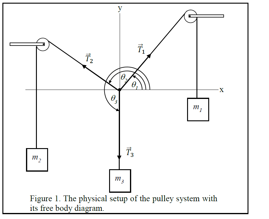
Solved 2 3 Figure 1. The physical setup of the pulley system ...
FREE-BODY DIAGRAMS (Section 5.2) 2. Show all the external forces and couple moments. These typically include: a) applied loads, b) support reactions, and, c) the weight of the body. Idealized model Free-body diagram (FBD) 1. Draw an outlined shape. Imagine the body to be isolated or cut "free" from its constraints and draw its outlined shape.

Determining tension and free body diagrams for a three-stage ...
Free-Body Diagram: Pulley C PROBLEM 2.69 A load Q is applied to the pulley C, which can roll on the cable ACB. The pulley is held in the position shown by a second cable CAD, which passes over the pulley A and supports a load P. Knowing that P = 750 N, determine (a) the tension in cable ACB, (b) the magnitude of load Q Hence: -O: TAcB(cos250 (750

Someone can help me with the free body diagram of the left ...
Check to see that every pulley that the belt rides is rotating. It should be pretty stiff, but if you can't turn it at all, something is locked up. Disengage the drive system (remove the belt, etc.) Try to turn the transmission drive pulley with your hand. Also check the movement of the pump, and any tensioner or idler pulley that may be present.

LabNewtonLaw.pdf - Newton\u2019s Laws PRE-LAB QUESTIONS Pre ...
The tensions in the 2 parts of cord (left of pulley and below pulley) exert a force on the pulley and hence on . The horizontal component of this force is what causes to accelerate left. The natural tendency of is to move vertically downwards. But since this occurs while the pulley is moving left, the cord attached to gets tilted.
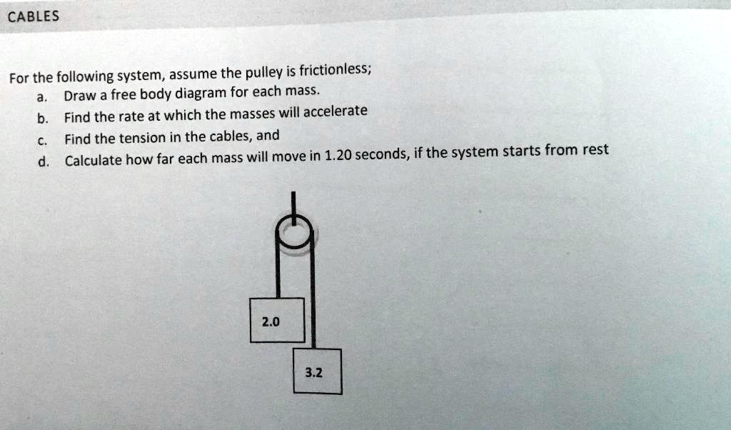
SOLVED:CABLES For the following system, assume the pulley is ...
Using the pulley system illustrated to the right below as an example, the basic method for discussed. As in Lessons 15, 16 and 17, the basic method is to draw a free body diagram of the forces involved, write an expression for the net force, and then solve for the acceleration. In a pulley system two masses are strung over a pulley. Note that ...

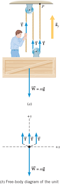
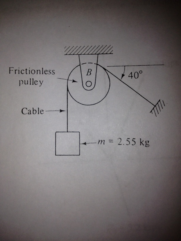
The 2.55-kg block in Fig. 3.5(a) is supported by a cable that ...
Remember that a free-body diagram must only include the external forces acting on the body of ... A light rope is attached to it and runs over a pulley.Definition of weight, vector form: →w=m→gw...Definition of weight, scalar form: w=mgw=mgNewton’s second law, vector form: →Fnet=∑...Newton’s second law, component form: ∑→Fx...

A free-body diagram that is typical of what is found in ...
The pulley is a solid disk with a mass of 1.25 kg and an unknown radius. The rope passes over the pulley on the outer edge. What is the acceleration of the blocks? As usual, the first place to start is with a free-body diagram of each block and the pulley.

Friction solved problems
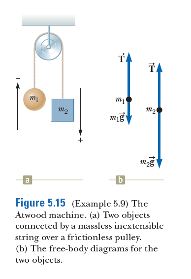
Answered: TA TA + m2 m2 mig mog b Figure 5.15… | bartleby
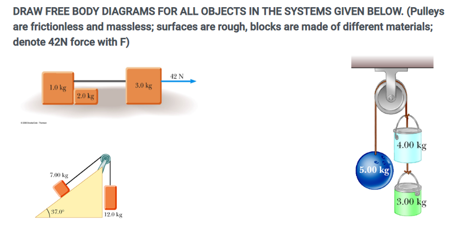
Solved DRAW FREE BODY DIAGRAMS FOR ALL OBJECTS IN THE | Chegg.com
Free Body Diagrams - Wikiversity
Vector statics) Effect of a pulley on free body diagram ...

Free Body Diagrams For any complicated situation, Isolate each object;

Part 4
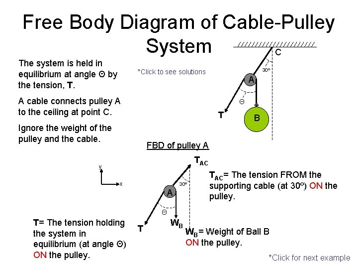
Free Body Diagram of CablePulley System C The

Pulleys - Physics for K-12 - OpenStax CNX
Multiple forces acting on an object | StudyPug
Using a Free Body Diagram to Understand Simple Pulleys ...
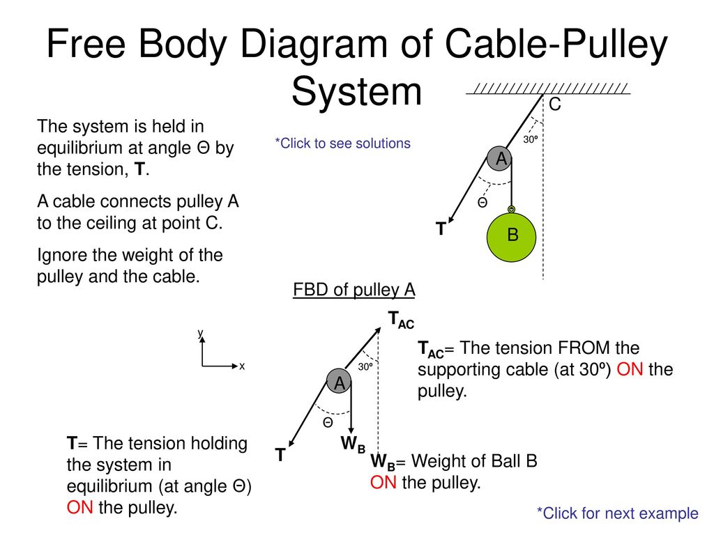
Free Body Diagram of Cable-Pulley System - ppt download

Free body diagram for string on half atwood machine - Imgur

Free Body Pulley 2

Statics eBook: Equilibrium & Free Body Diagrams

Pulleys - Physics for K-12 - OpenStax CNX

Solved a) Draw the free body diagram for pulley A. b) Draw ...

Free Body Diagrams, Tutorials with Examples and Explanations

A pulley system — Collection of Solved Problems
Drawing free body diagrams of boxes linked by strings over a ...
Interaction between an ideal pulley and an ideal rope ...
Free Body Diagrams Principles of Engineering 2012 Project

The Free Body Diagrams Of The Two Hanging Masses Of - Newtons ...
Constant Acceleration Pre-lab Assignment
0 Response to "45 free body diagram for pulley"
Post a Comment