42 control 4 wiring diagram
PPC-4 Thermal Post Purge Kit Installation Manual & Wiring ... April 10, 2019. Super Admin. Installation Manual and Wiring Diagram for model PPC-4 Thermal Post Purge Kit. English. previous post: SC100 Installation Instructions. next post: PPC-5 Electronic Post Purge Kit Installation Manual & Wiring Diagram. Emcp 4.2 Wiring Diagram Emcp 4.2 Wiring Diagram. 5 EMCP AND ELECTRICAL DIAGRAMS. sensors will typically be wired to the engine ECM and the EMCP 4 will get that information from the engine. EMCP Auto-start control panel (upgraded to NFPA 11 0) .. 2-wire, 3-wire and 4-wire RTD inputs. Three Phase Wiring Diagram.
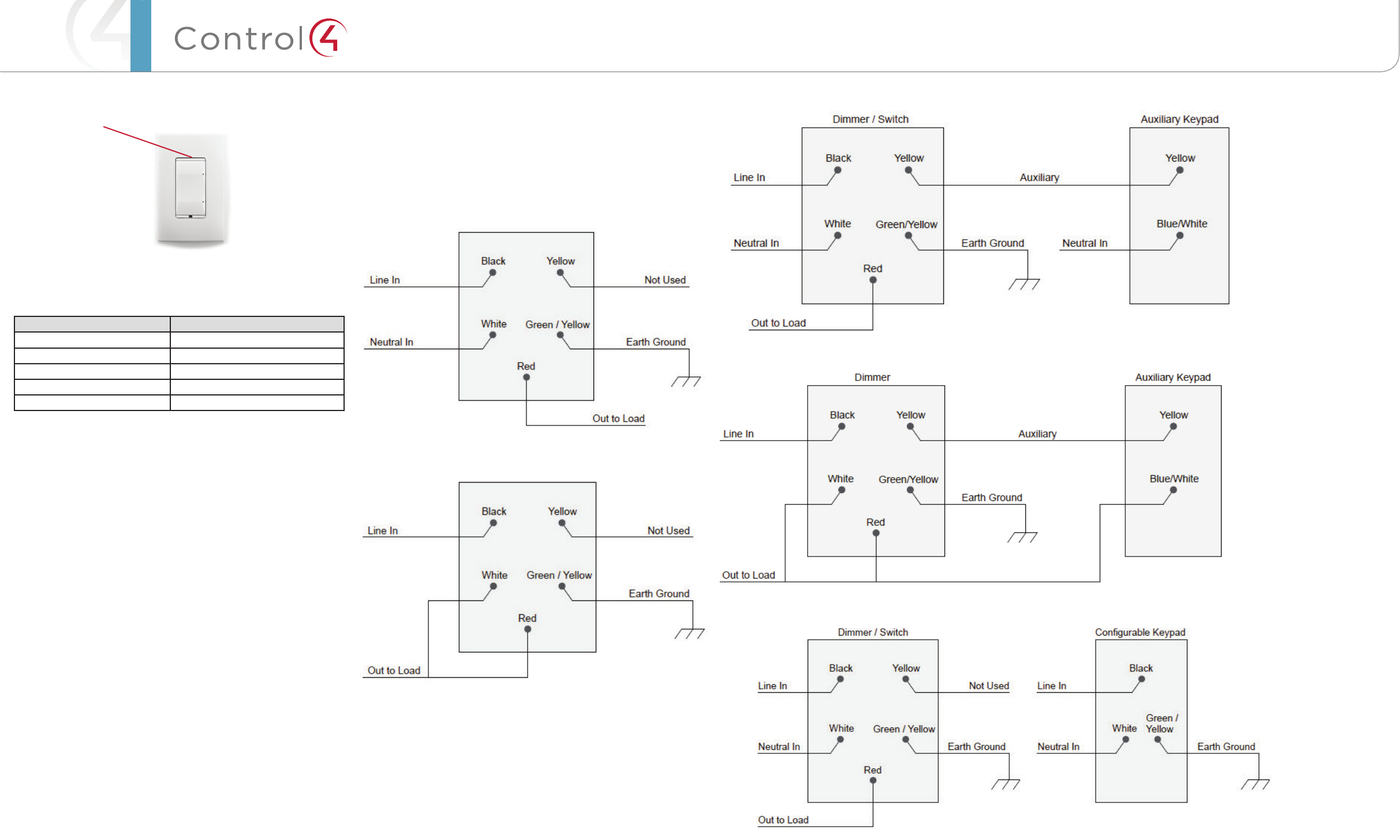
PDF Essential Lighting Wiring Guide - Control4 This diagram shows a sample 4-way wiring configuration using an Essential Forward Phase Dimmer (C4-V-FPD120) or Switch (C4-V- SW120-277) with two Essential Auxiliary Keypads (C4-V-AUX). Daisy-chain each additional Auxiliary Keypad by extending the Ground, Traveler, and Neutral to each keypad. 4-way configuration

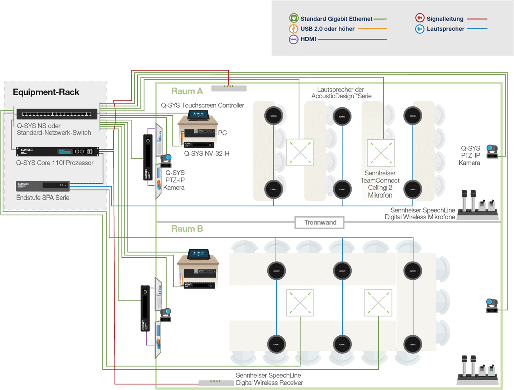
Control 4 wiring diagram
Control Panel Wiring Diagrams - Wiring Diagram and ... Self Adhesive Wiring Diagram For Control Panel Rangvishwa Enterprises Id 10541553097. Basic Electrical Design Of A Plc Panel Wiring Diagrams Eep. Bernini Design 160kva Ats Control Panel Wiring Diagram The Be28 Panels Are Manufactured In Range 15 Up To Basic Configuration Features An Alarm Output Relay And Two Configurable. Trailer Wiring Diagram 4 Wire - Wiring Sample This guide will be discussing 4 wire trailer wiring diagram troubleshooting. The four wires control the turn signals brake lights and taillights or running lights. 4 way trailer connectors are. Start by cutting the white wire and attaching it to the trailer frame. Can trailer 4 way be ran to trailer with 8 wires for trailer wiring. Wiring Diagram Engine Control 4a Fe The FA20D engine had a 4-2-1 exhaust manifold and dual tailpipe outlets. To reduce emissions, the FA20D engine had a returnless fuel system with evaporative emissions control that prevented fuel vapours Bose 6 Pin Lemo Headset Install Connector Kit | Aircraft Use your vehicle repair manual to check the wiring diagram for that circuit.
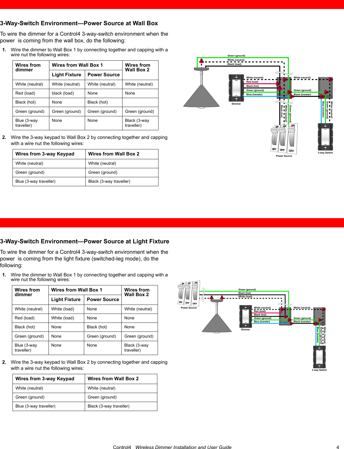
Control 4 wiring diagram. PDF Control4® Panelized Lighting: Reference Guide for Electricians Figure 1). Panelized lighting utilizes a centralized/star wiring configuration, where circuits from the breaker box are routed first to a centrally-located enclosure (panel), which houses dimmer, relay, and other system control modules. From there, the switched/dimmed circuits are routed directly to the loads (see Figure 2). Control4 Ldz-101 Wiring Diagram 3 Way Switch Control4 Ldz-101 Wiring Diagram 3 Way Switch 19.10.2018 4 Comments So, the control4 diagram example is different. Line in downstairs (where and three way switches. C4 really just simulates a three way switch. LSZX Wireless Switch Exhibit 8 details for FCC ID R33LSZ made by at Wall Box To wire the switch for a Control4 3-way-switch environment when. 4 Wire Light Switch Wiring Diagram - The Wiring A 4 way switch wiring diagram is the clearest and easiest way to wire that pesky 4 way switch. Hunter Ceiling Fan Wiring Diagram Switch. 4-Way Switch Wiring Diagram: For example, you may want to control a ceiling light in the basement from the top of the stairs, from the bottom of the stairs, and from a door leading to the outside. PDF for existing homes & new construction - Control4 other seamlessly. If done correctly, proper wiring can save money, time and frustration. The type of wiring required for a home automation system is called structured wiring. Structured wiring is a general term that refers to a whole-house network of audio, video, data, telephone, home automation components or security signals.
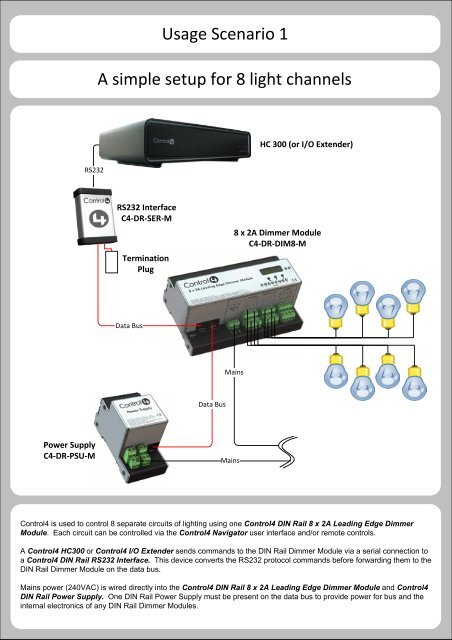
Ddec 4 Wiring Diagram - schematron.org The wire. ecm wiring diagram car cable and detroit diesel series 60 best, ddec iv wiring diagram series 60 youtube lively 4 ecm, ddec 4 ecm wiring diagram ii.a DDEC II to DDEC IV conversion is made on a vehicle using the DDEC II cruise control feature. Control 4 Wiring Diagrams - Wiring View And Schematics Diagram Control 4 Wiring Diagrams. By Margaret Byrd | July 10, 2018. 0 Comment. Control4 c4 din 8dim e 8 channel dimmer guide manualzz 8tv 0 10v wiring three way question answer c4forums the community 8rel relay terminalblockwiringguide online panelized lighting reference for electricians c4dim1z wireless user manual 200 00143 wirelessdimmer 600w ... PDF 8-Channel Dimmer Wiring Guide - Control4 Wiring Guide Diagrams Color Code: Black Line Red Load Grey Neutral Green Earth Ground Blue Ethernet Figure 1. Wiring in Control4 Panel Wiring Diagrams Use the Control4® 8-Channel Dimmer wiring diagrams along with the 8-Channel Dimmer Installation Guide to install 8-Channel Dimmers. ™ Fabulous Control4 Wiring Schematic Sew Motor Diagram Assortment of control 4 wiring diagram. A wiring diagram is a simplified traditional photographic representation of an electric circuit. The following tips apply to either a new home or an existing home.
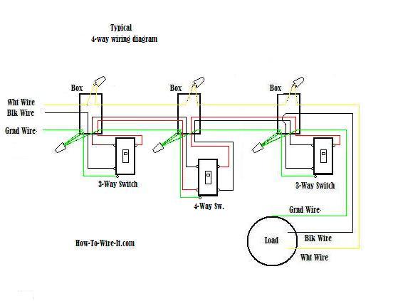
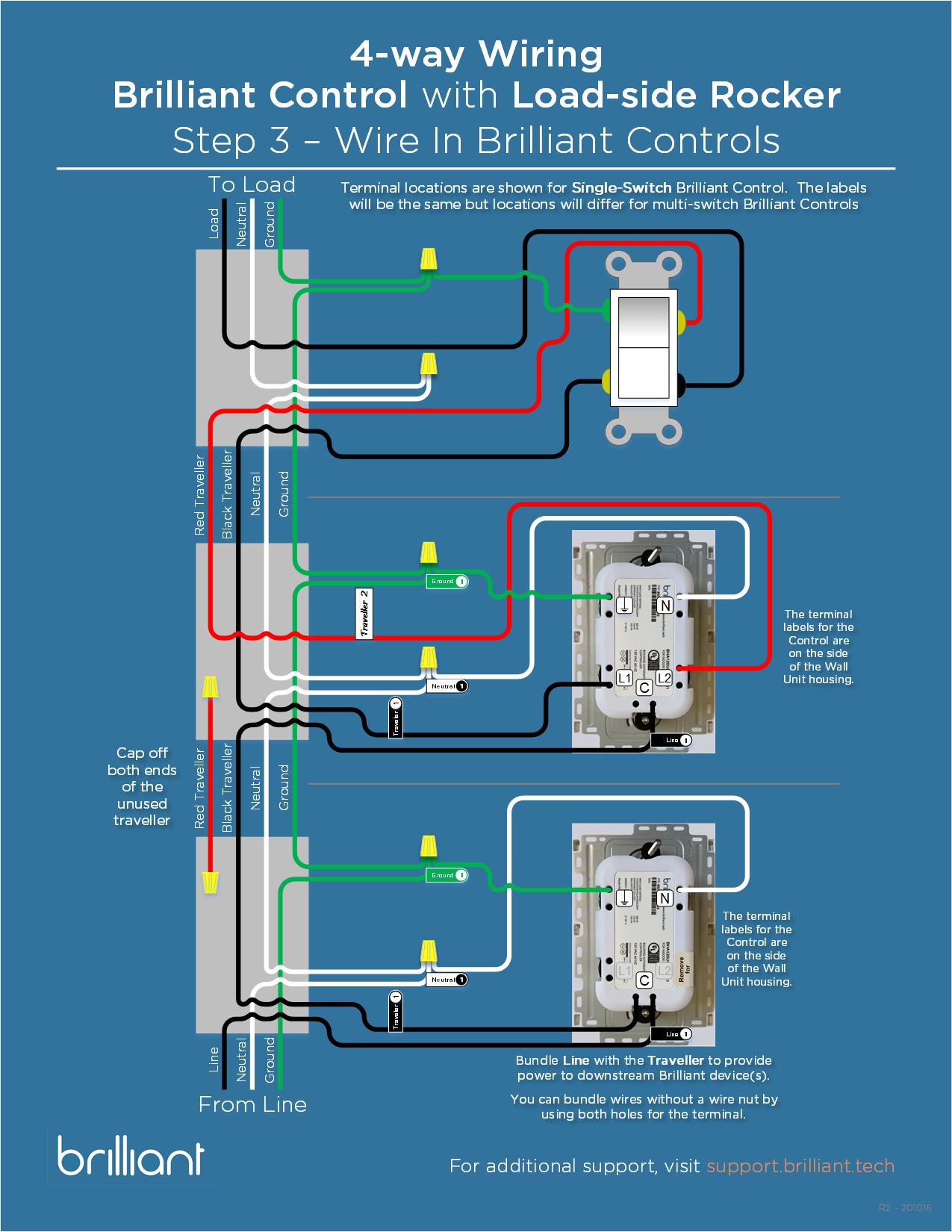
PDF Configurable Wired Keypad Installation Guide ctrl4.co/buswiring Wiring diagrams For bus wiring details, refer to the Keypad Bus Wiring Guide(ctrl4.co/buswiring). Operation and configuration On initial power up, all status LEDs on the keypad will illuminate green, indicating that the device has power. Until the keypad has been configured into a Control4 system, it will not control any loads. Control 4 Switch Wiring Diagram - Wiring Diagram And ... Wiring Diagram For 4-way switch: More than three locations to control light fixtures utilizes 3-way switches at the end of the switched circuit and 4-way switches in the middle. Emcp 4.2 Wiring Diagram - schematron.org Emcp 4.2 Wiring Diagram. 5 EMCP AND ELECTRICAL DIAGRAMS. If battery charger fault condition wiring is connected to the EMCP Digital Inputs and these Digital Inputs are. EMCP simulator was designed to provide a way to demonstrate some of the Figure 1 shows a simplified schematic of the 3-phase wiring. EMCP simulator was designed to provide a way ... Control 4 Wiring Diagram Collection Collection of control 4 wiring diagram. A wiring diagram is a simplified conventional photographic representation of an electric circuit. It shows the elements of the circuit as streamlined forms, and the power and signal connections in between the tools.
Control 4 Wiring Diagram - Free Wiring Diagram Variety of control 4 wiring diagram. A wiring diagram is a simplified traditional photographic representation of an electric circuit. It shows the components of the circuit as streamlined shapes, and the power as well as signal links between the gadgets.
Control4 Thermostat Wiring Diagram - schematron.org Control4 Thermostat Wiring Diagram. Control4 Wireless Thermostat Installation Guide and the Control4. Wireless Thermostat User Guide. IMPORTANT! Using this product in a manner other than . This Control4® Wireless Thermostat enables intelligent HVAC control as part of a Changing this setting is described in Step 14, "Installation Instructions.
Honeywell 4 Wire Thermostat Wiring Diagram - easywiring Honeywell 4 wire thermostat wiring diagram. Mounting plate with four wires of the honeywell large dial thermostat model t87n1026. The next t stat the honeywell t8775c1005 2 non programmable t stat can control both heating and cooling as well as manual fan operation with just four wires. Honeywell thermostat wiring diagram 4 wire source.
PDF Basic Wiring for Motor Contol - Eaton control circuit may not be at the same voltage as the power circuit. When the voltage of the control and power circuits is the same, it is referred to as Common Control. If the volt-ages are different, it is called Separate Control. Figure 4. Typical Starter Wiring Diagram — Three-Phase Separate voltages supplied by different voltage sources.
Cal Spas Model Ps-4 Control Box Wiring Diagram - Portable ... Does anyone have a wiring diagram for a 1993 PS-4 control box? or tell me where I can find one? I'm not having a whole lot of luck here. Some one has tamperd with the one I have and I want to make sure I have it corrected befor I power it up. thanks
Powerflex 4 Wiring Diagram The examples and diagrams in this manual are included solely for illustrative PowerFlex 4 User Manual, Publication 22A-UMJ-EN-E. The information below summarizes changes made for the September PowerFlex 4 User Manual, P-4 Chapter 1 Installation/Wiring. Position 12 of the Catalog Number now indicates drive type.
PDF Brake Control Wiring Diagram - AnythingTruck.com Generic Wiring Diagram READ THIS FIRST: Read and follow all instructions carefully before wiring brake control. Keep these instructions with the brake control for future reference. Important Facts to Remember 1. The brake control must be installed with a 12 volt negative ground system.
Control4 Home Automation Wiring Diagram - U Wiring Control4 home automation wiring diagram. A wiring diagram is a streamlined standard pictorial representation of an electrical circuit. It installs in a standard back box using typical wiring standards and communicates to the Control4 system using a wireless connection. Control 4 Wiring Diagram General Wiring Diagram.
PDF Telecaster 4-Way Wiring Diagrams - Atlantic Custom Guitars Telecaster 4-Way Wiring Diagrams This wiring diagram assumes you are using a metal control plate. If you are not using a metal control plate, you will need to run a small ground wire from the volume pot to the tone pot. Wiring diagram courtesy Seymour Duncan Pickups Wiring diagram courtesy Seymour Duncan Pickups
PDF wiring diagram #7 4-way wiring - Lutron Electronics, Inc. 1.800.523.9466 dimmers create ambiance and save energy Lutron | 191 Lutron ® | wiring diagrams wiring diagram #6 3-way wiring Control Line Side 3-Way Switch Dimmer, Switch, Fan Control Dimmer, Switch, Fan Control Lighting Load
Standard Control4 Wiring Diagrams - Driver Discussion ... Standard Control4 Wiring Diagrams Standard Control4 Wiring Diagrams. By andy.cytexone, January 6, 2006 in Driver ... the designing phase of a new home and was thinking about incorporating C4 in my house while the house is all studs and wiring is being pulled. Link to comment Share on other sites. More sharing options... Gene. Posted ...
Wiring Diagram Engine Control 4a Fe The FA20D engine had a 4-2-1 exhaust manifold and dual tailpipe outlets. To reduce emissions, the FA20D engine had a returnless fuel system with evaporative emissions control that prevented fuel vapours Bose 6 Pin Lemo Headset Install Connector Kit | Aircraft Use your vehicle repair manual to check the wiring diagram for that circuit.
Trailer Wiring Diagram 4 Wire - Wiring Sample This guide will be discussing 4 wire trailer wiring diagram troubleshooting. The four wires control the turn signals brake lights and taillights or running lights. 4 way trailer connectors are. Start by cutting the white wire and attaching it to the trailer frame. Can trailer 4 way be ran to trailer with 8 wires for trailer wiring.
Control Panel Wiring Diagrams - Wiring Diagram and ... Self Adhesive Wiring Diagram For Control Panel Rangvishwa Enterprises Id 10541553097. Basic Electrical Design Of A Plc Panel Wiring Diagrams Eep. Bernini Design 160kva Ats Control Panel Wiring Diagram The Be28 Panels Are Manufactured In Range 15 Up To Basic Configuration Features An Alarm Output Relay And Two Configurable.














0 Response to "42 control 4 wiring diagram"
Post a Comment