43 ts diagram carnot cycle
Carnot Cycle Tv Diagram - schematron.org A Carnot gas cycle operating in a given temperature range is shown in the T-s diagram in Fig. (a). One way to carry out the processes of this cycle is through . Isothermal process on p-V, T-V, and p-T diagrams isothermal ⇒ T = T. 0. = constant Winter , Prof. Clarke. Rankine Cycle - Ts, Pv Diagrams, Reheat, Equations ... If you can see in the above image the process 1-2 and 3-4 are shown via the vertical lines. They are like a Carnot cycle. So, obviously, the actual Rankine cycle will be different from the ideal ones. The losses are accounted and the entropy is varied. Rankine Cycle with P-v Diagram. Let's see the P-v diagram,
COP Of Air Refrigerator Working On Reversed Carnot Cycle ... Fig (1) and fig (2) shows the p-v and T-s diagram of a refrigeration system working on reversed Carnot cycle. The process involved in reversed Carnot cycles are as follows 1-2. isentropic compression process During this stage, air is compressed isentropically. Pressure and temperature increases, the specific volume of decreases.
Ts diagram carnot cycle
Carnot Cycle | Carnot Heat Engine | Efficiency, P-V & T-S ... Below are P-V and T-S Diagrams of the Carnot Cycle. We know T4 = T1, say it be TA and T3 = T2, say it be TB. Below is the table which shows heat and work interactions of the Carnot cycle, along with the change in the internal energy. Net Work of a Cycle = Enclosed Area on a TS Diagram Net Work of a Cycle = Enclosed Area on a TS Diagram Carnot Cycle represented on a TS Diagram. = Area below line segment 1-2 = Area below line segment 3-4 Apply the 1st Law to the Carnot Cycle : Q H - Q C = W net Therefore, the area enclosed by the path of a cycle on a TS Diagram represents the net work for the cycle. Clockwise Counter-clockwise HE Carnot Vapour Cycle - Components - PV Diagram - TS Diagram ... In this video, I explained following topic of Carnot Vapour Cycle.Components and arrangement of carnot vapour cycle.PV and TS diagram of carnot vapour cycle...
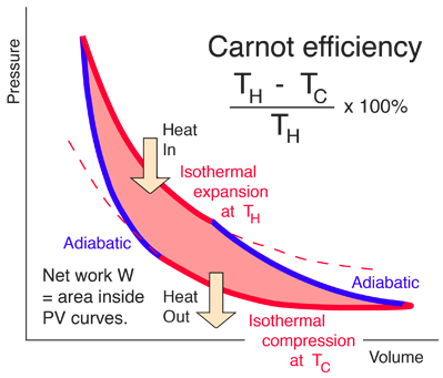
Ts diagram carnot cycle. Carnot Cycle - pV, Ts diagram | Processes | nuclear-power.com The temperature-entropy diagram (Ts diagram) in which the thermodynamic state is specified by a point on a graph with specific entropy (s) as the horizontal axis and absolute temperature (T) as the vertical axis, is the best diagram to describe behaviour of a Carnot cycle. Carnot cycle: p-V diagram and T-S diagram 3.5 Carnot cycle: p-V diagram and T-S diagram. In what follows we discuss one of the most important concepts of thermodynamics, the Carnot cycle. In general in a circular process the thermodynamic system passes several exchange points until it ends up in its starting point. It is important to note that for different branches the surrounding can ... Draw the reversed carnot cycle on P-V and T-S diagrams and ... The Carnot refrigerator works on the reversed Carnot cycle. A reversed Carnot cycle using air as working medium is shown on p-v and t-s diagrams. The processes involved during the cycle are: Fig. Reversed Carnot Cycle. 1. Isentropic compression process- Air is compressed is entropically as shown by curve 1-2 on diagrams. No heat is absorbed or ... Ericsson Cycle Pv and Ts Diagram - Understanding Business ... If we think the concept of regeneration where, area under 2-3 i.e. Q 2-3 and area under 4-1 i.e. Q 4-1 are equal, Regenerative Ericsson cycle will become Carnot cycle because heat energy will be added from an external source at constant temperature and heat will be rejected too to an external sink at constant temperature and hence Regenerative ...
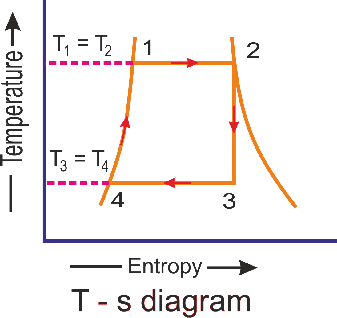
Carnot Cycle - Thermodynamics - Engineering Reference with ... The Carnot Cycle can be represented on a TSdiagram (see Figure 9), which is useful for calculating the Carnot Cycle efficiency. Figure 9 To calculate the thermal efficiency, first calculate the QSand QRterms (see Eq. 4). Carnot Cycle Represented on a T-S Diagram - Learn Thermo Ch 7, Lesson B, Page 15 - Carnot Cycle Represented on a T-S Diagram Steps 1-2 and 3-4 are isothermal, so it should come as no surprise to learn that these steps are horizontal lines on a TS Diagram. But, did you anticipate that steps 2-3 and 4-1 would be vertical lines ? Cool, eh ? And what's up with the shading on this diagram? Carnot cycle: Definition, Formula, Pv and Ts Diagram ... Carnot cycle has maximum efficiency for engine working between two different temperatures T H T H (heat source temperature) & T L T L (Sink temperature). For Example:- Heat Engine working between source temperature 400 kelvin & Sink temperature 350 Kelvin, For this Carnot efficiency is given by ηth = 1 − T H T L η t h = 1 - T H T L PDF Refrigeration Cycle - Simon Fraser University The Reversed Carnot Cycle Reversing the Carnot cycle does reverse the directions of heat and work interactions. A refrigerator or heat pump that operates on the reversed Carnot cycle is called a Carnot refrigerator or a Carnot heat pump. Fig. 5-1: T-s diagram and major components for Carnot refrigerator.
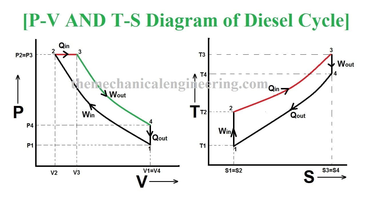
Carnot cycle - Wikipedia : A Carnot cycle as an idealized thermodynamic cycle performed by a heat engine (Carnot heat engine), illustrated on a TS (temperature T-entropy S) diagram. The cycle takes place between a hot reservoir at temperature T H and a cold reservoir at temperature T C. The vertical axis is the system temperature, the horizontal axis is the system ... Power cycles Otto,Diesel, Carnot,Brayton,Dual cycle Problems On Power cycles :Carnot cycle PROBLEMS A A Carnot engine working between 650K and 310 K produced work of 150 KJ, Find the thermal efficiency and heat added during cycle. An ideal engine working on Carnot cycle receives heat at 590 K and rejects at 295 K. If it absorbs heat at the rate of 35 KJ/sec Calculate the work done per Sec. What is Carnot Cycle - pV, Ts diagram - Definition The temperature-entropy diagram (Ts diagram) in which the thermodynamic state is specified by a point on a graph with specific entropy (s) as the horizontal axis and absolute temperature (T) as the vertical axis, is the best diagram to describe behaviour of a Carnot cycle. Diesel Cycle: Definition, Process, PV and TS Diagram ... From the PV and TS Diagram the process 1 to 4 we will list some of the important terms, So here we find out the efficiency of diesel engine. Diesel Cycle Efficiency: The efficiency of the diesel cycle is more efficient than the Otto cycle but not more than the Carnot cycle which is having 75 Percent.
Diesel Cycle: Definition, Process, PV and TS Diagram ...
Ts Diagram Carnot Cycle - schematron.org The Carnot cycle is a theoretical thermodynamic cycle. During this step (A to B on T-S diagram, 1 to 2 P-V diagram) the expanding gas makes.Ts diagram of Carnot cycle. The area under the Ts curve of a process is the heat transferred to the system during that process.

File:T-s diagram Carnot cycle.svg - Wikimedia Commons
Carnot Cycle: Derivation, Stages & Qualities - Physics ... The Carnot cycle is a theoretical thermodynamic cycle proposed by Nicolas Léonard Sadi Carnot in 1824 and expanded by Benoit Paul Émile Clapeyron in the 1830s and 40s. It can be shown that it is the most efficient cycle for converting a given amount of thermal energy into work, or conversely, creating a temperature difference (e.g ...
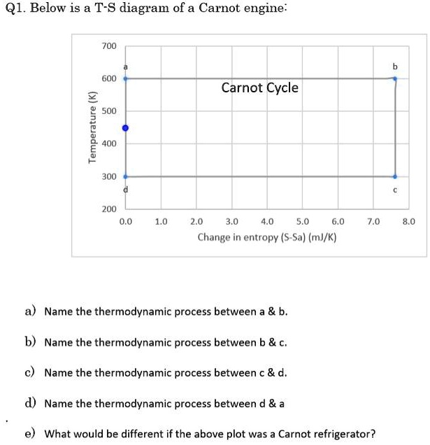
SOLVED:Q1. Below is a T-S diagram of a Carnot engine: 700 600 ...
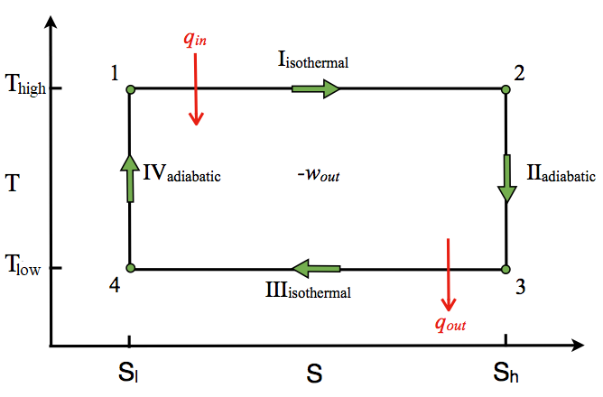
The T-S Diagram of the Carnot Cycle Show the Carnot cycle ... Analysis Recall that the Carnot cycle is made up of two reversible isothermal (T= constant) processes and two isentropic (s= constant) processes. These four processes form a rectangle on a T-S diagram, as shown in Fig. 7-19. On a T-S diagram, the area under the process curve represents the heat transfer for that process. Thus the area

Carnot Cycle | Carnot Heat Engine | Efficiency, P-V & T-S ...
Efficiency and TS diagram for carnot cycle in Hindi by the ... Hello friends in this video I'm talking about what is the efficiency of carnot cycle in terms of Entropy and TS diagram for carnot cycle so please watch it a...

What is Otto Cycle - pV, Ts Diagram - Definition
Carnot cycle in T-S diagram. | Download Scientific Diagram without thermal gradients between the "working fluid" and the thermostats, the heat flow rate involved are zero which according to the first law of thermodynamics leads to the paradoxical fact that...

3. Reversed Carnot Refrigeration cycles
Carnot heat engine - Wikipedia A Carnot heat engine is a heat engine that operates on the Carnot cycle.The basic model for this engine was developed by Nicolas Léonard Sadi Carnot in 1824. The Carnot engine model was graphically expanded by Benoît Paul Émile Clapeyron in 1834 and mathematically explored by Rudolf Clausius in 1857, work that led to the fundamental thermodynamic concept of entropy.

Solved The T-s diagram shows the Carnot cycle. Draw the ...
Carnot Vapour Cycle Processes with [P-v and T-s] Diagram A Carnot cycle steam as a working substance is represented on the p-v and T-s diagram in Figure. Carnot Vapour Cycle P-V Diagram Carnot Vapour Cycle T-S Diagram Consider 1 kg of saturated water at pressure p1, and absolute temperature T1, as represented by point 1 in the figure.
Rankine Cycle - Ideal Rankine Cycle efficiency ...
Carnot Cycle: Working Principle & Processes with [Pv - Ts ... Now, let us consider the four stages of Carnot's cycle. Let the engine cylinder contain m kg of air at its original condition represented by point 1 on the p-v and T-s diagrams. At this point, let p1, T1, and v1 be the pressure, temperature, and volume of the air, sequentially. Carnot Cycle Processes Isothermal Expansion

Thermodynamics eBook: Tds Relations
Carnot Cycle - NASA We will use a p-V diagram to plot the various processes in the Carnot Cycle. The cycle begins with a gas, colored yellow on the figure, which is confined in a cylinder, colored blue. The volume of the cylinder is changed by a moving red piston, and the pressure is changed by placing weights on the piston.

Ts Diagrams Carnot Cycle Stock Vector (Royalty Free) 2085952840
What is Otto Cycle - pV, Ts Diagram - Definition Carnot Cycle - pV, Ts diagram pV diagram of Otto Cycle. The area bounded by the complete cycle path represents the total work that can be done during one cycle. The Otto cycle is often plotted on a pressure- volume diagram ( pV diagram) and on a temperature-entropy diagram (Ts diagram).

Carnot cycle|Concept|How to derive efficiency of Carnot cycle ...
Carnot Cycle -Definition, Theorem, Efficiency, Diagrams ... Carnot's Cycle Proof First Part To prove the first part of the theorem, we consider two engines R and I working between the temperatures T 1 and T 2 where T 1 > T 2 (Fig.). Of these two engines, R is reversible and I is irreversible. Suppose I is more efficient than R.

Carnot cycle on T-s diagram | Mechanical engineering ...
Carnot Vapour Cycle - Components - PV Diagram - TS Diagram ... In this video, I explained following topic of Carnot Vapour Cycle.Components and arrangement of carnot vapour cycle.PV and TS diagram of carnot vapour cycle...

6(a): Ideal Carnot Cycle T-S Diagram Tmin | Download ...
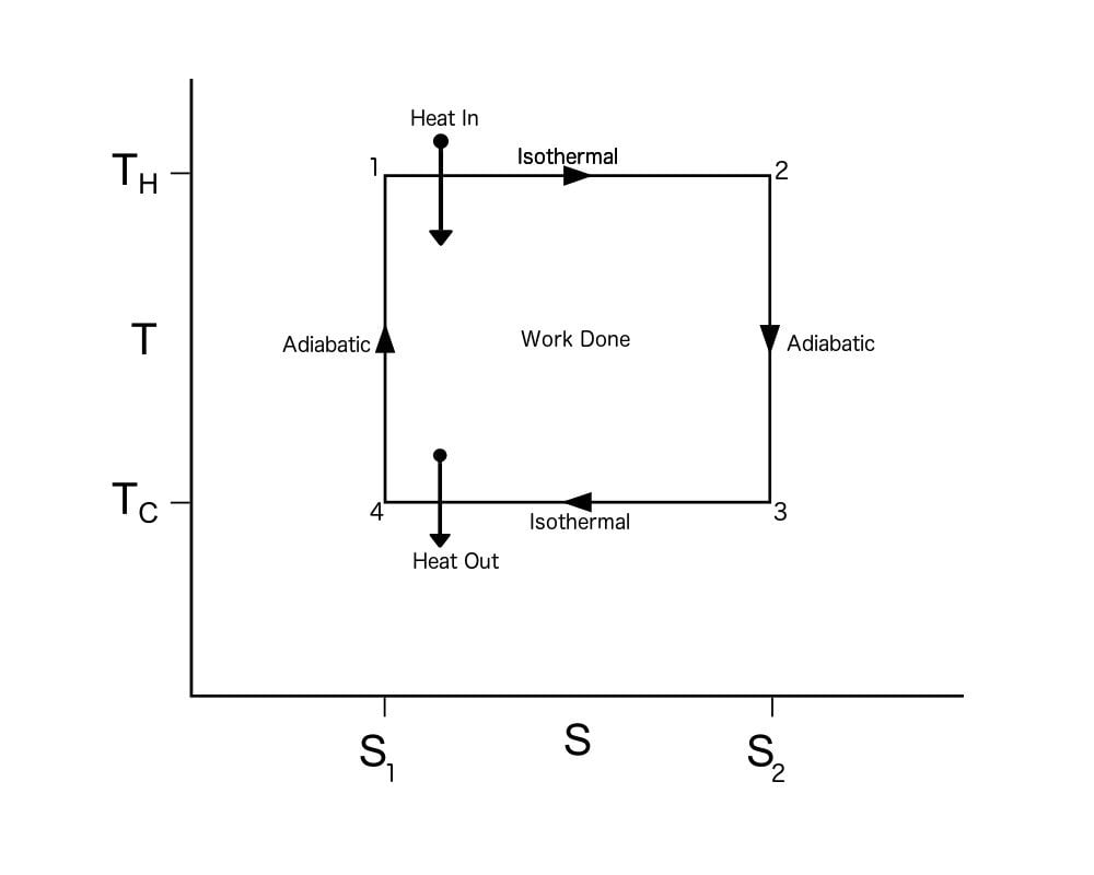
Net Work of a Cycle = Enclosed Area on a TS Diagram Net Work of a Cycle = Enclosed Area on a TS Diagram Carnot Cycle represented on a TS Diagram. = Area below line segment 1-2 = Area below line segment 3-4 Apply the 1st Law to the Carnot Cycle : Q H - Q C = W net Therefore, the area enclosed by the path of a cycle on a TS Diagram represents the net work for the cycle. Clockwise Counter-clockwise HE

File:Carnot Cycle T-S diagram.svg - Wikimedia Commons
Carnot Cycle | Carnot Heat Engine | Efficiency, P-V & T-S ... Below are P-V and T-S Diagrams of the Carnot Cycle. We know T4 = T1, say it be TA and T3 = T2, say it be TB. Below is the table which shows heat and work interactions of the Carnot cycle, along with the change in the internal energy.

Thermodynamics eBook: Carnot Refrigerator and Heat Pump
What Is Carnot Cycle Or Engine? » Science ABC
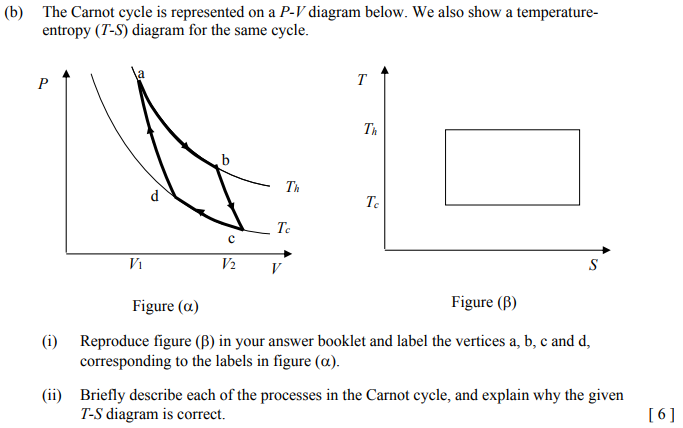
Solved (b) The Carnot cycle is represented on a P-V diagram ...

12 Carnot cycle on P-V and T-s diagrams | Download Scientific ...

COP Of Air Refrigerator Working On Reversed Carnot Cycle with ...

The T-S Diagram of the Carnot Cycle Show the Carnot cycle on ...
Carnot Cycle - Chemistry LibreTexts

File:Carnot-cycle-T-S-diagram.svg - Wikimedia Commons

The figure below provides the T-s diagram of a Carnot heat ...

Objectives_template
Carnot Vapour Cycle Processes with [P-v and T-s] Diagram
Solved] Carnot Cycles a- Discuss the Carnot cycle in P-V and ...
What is the T-s diagram for the Carnot refrigeration cycle ...

STIRLING CYCLE PV AND TS DIAGRAM - UNDERSTANDING BUSINESS ...

Carnot Cycle | Carnot Heat Engine | Efficiency, P-V & T-S ...

Figure provides the T-s diagram of a Carnot heat pump cycle ...
Heat Rejection Waste Heat Thermodynamics | Engineers Edge

P-V diagram | Blog of Willy Yanto Wijaya

Carnot Refrigeration Cycle, Refrigeration Cycle, Assignment Help
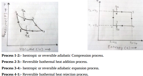
Draw P-V and T-S diagram for carnot cycle. Name the processes ...

Complete Carnot Cycle, efficiency, PV diagram, TS diagram ...

2: Reversed Carnot Cycle (a) Schematic Drawing (b) T-S ...

Reverse Carnot Cycle Efficiency | Matt Evans

Carnot Vapour Cycle - Components - PV Diagram - TS Diagram - Efficiency - Limitation

Carnot posted by Sarah Walker
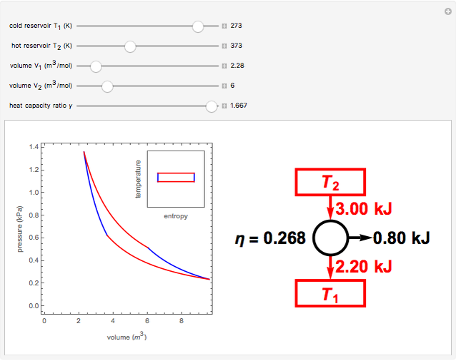
Carnot Cycle on Ideal Gas - Wolfram Demonstrations Project

Draw P-V diagram for Carnot cycle. Write the name of ...
Carnot Cycle

Carnot Cycle Processes : Efficiency, FAQs, Problems, Theorem
0 Response to "43 ts diagram carnot cycle"
Post a Comment