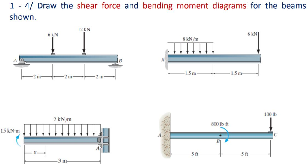
44 shear force and bending moment diagram examples
Sign convention for shear force and bending moment diagram... We were discussing meaning and importance of shear force and bending moment and also some basic concepts of strength of materials in our recent posts. We have already seen the various types of beams and different types of loads on beam during our previous posts. Chapter 8. Shear Force and Bending Moment Diagrams for... 1 hapter 8 Shear Force and ending Moment Diagrams for Uniformly Distributed Loads. diagrams for a beam carrying distributed load over its entire length. 9 More Examples Involving Uniformly Distributed Loads Draw the shear force and bending moment diagrams for each of the beams...
PDF Bending Moment & shear force Shear and bending-moment diagrams for this loading condition are shown in Figs (d) and (e). No axial-force diagram is necessary, as there is Problem 7: Bending Moment and Shear force For the beam as shown in Fig 5, express the shear V and the bending moment M as a function of x along...
Shear force and bending moment diagram examples
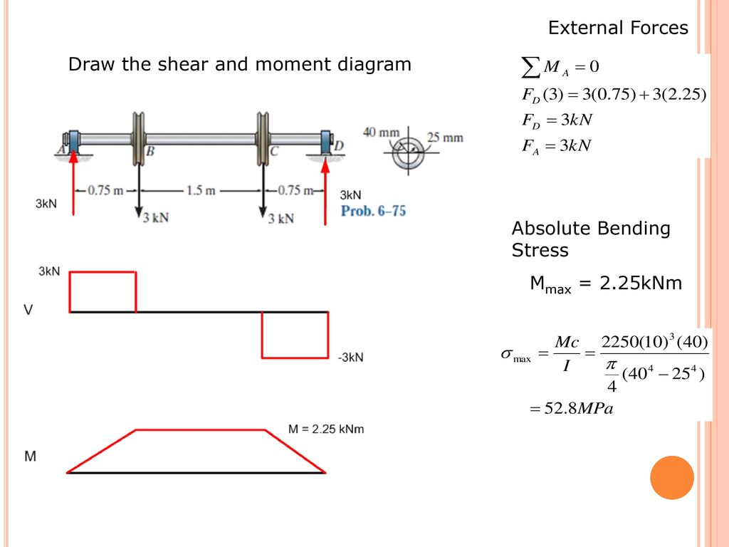
› maximum-shear-forceMaximum Shear Force - an overview | ScienceDirect Topics A beam of rectangular cross-section is subjected to a bending moment M (N·m) and a maximum shear force V (N). The bending stress in the beam is calculated as σ = 6M/bd 2 (Pa), and average shear stress is calculated as τ = 3V/2bd (Pa), where b is the width and d is the depth of the beam. The allowable stresses in bending and shear are 10 and ... 5.0 Drawing Shear Force and Bending Moment Diagrams - An... Without understanding the shear forces and bending moments developed in a structure you can't complete a design. Shear force and bending moment diagrams tell us about the underlying state of stress in the structure. So naturally they're the starting point in any design process. 4 Shear Forces and Bending Moments Draw the shear-force and bending-moment diagrams for beam ABC. Solution 4.5-8 273 Shear-Force and Bending-Moment Diagrams P P A Pa C B a a a a Beam with overhang P P C upper beam: a Pa a a P P P P B lower beam: C a a a 2P P V 0 M 0 P Pa Problem 4.5-9 Beam ABCD is...
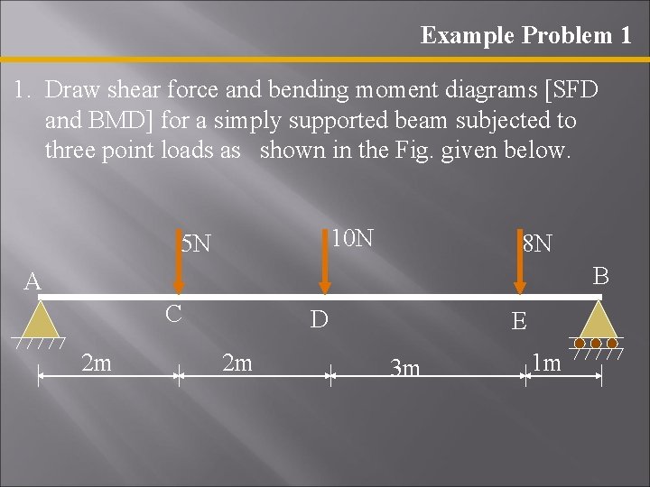
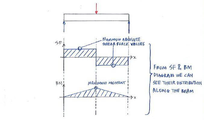
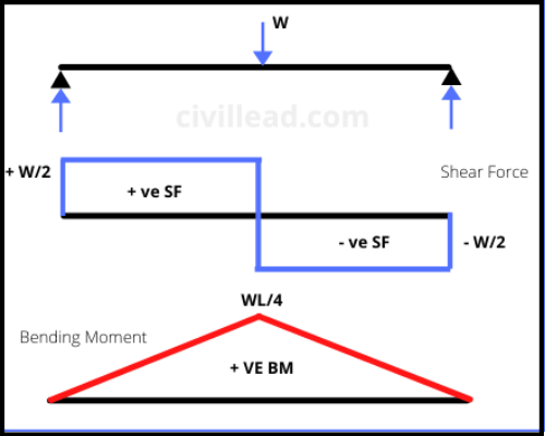
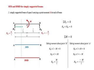
Shear force and bending moment diagram examples. PDF statics.dvi | Statics of Bending: Shear and Bending Moment Diagrams The moment diagram is now parabolic, always being one order higher than the shear diagram. following shows how the moment equation of this example might be plotted, using the Heaviside function to provide the singularity. Shear Force and Bending Moment Diagrams [SFD & BMD] Bending Moment Diagram (BMD): The diagram which shows the variation of bending moment along the length of the beam is called Bending Moment 10N 5N 8N B A C D 2m 2m 1m 3m E Example Problem 1 • Draw shear force and bending moment diagrams [SFD and BMD] for a simply... › sfd-and-bmdSFD and BMD - Shear force diagram and Bending Moment diagram SFD and BMD stand for the shear force diagram and the Bending moment diagram applied to the structure respectively. When you design or analyze any structure then you have to consider the total shear force and bending moment to get the required strength and durability of the structure. Shear Force & Bending Moment Diagram of Simply Supported Beam Shear force and bending moment diagram of simply supported beam can be drawn by first calculating value of shear force and Shear force and bending moment values are calculated at supports and at points where load varies. Simply Supported Beam with Point Load Example.
Shear Force and Bending Moment Diagrams | Medium Learning how to drawing shear force diagrams (SFDs) and bending moment diagrams (BMDs) is a necessary skill to learn for engineering students The quick way skips finding the full expressions and just identifies key points on the diagrams, and the type of curve that connects them. It's a more visual... Understanding Shear Force and Bending Moment Diagrams This video is an introduction to shear force and bending moment diagrams.What are Shear Forces and Bending Moments?Shear forces and bending moments are... 4 Shear Forces and Bending Moments Draw the shear-force and bending-moment diagrams for beam ABC. Solution 4.5-8 273 Shear-Force and Bending-Moment Diagrams P P A Pa C B a a a a Beam with overhang P P C upper beam: a Pa a a P P P P B lower beam: C a a a 2P P V 0 M 0 P Pa Problem 4.5-9 Beam ABCD is... 5.0 Drawing Shear Force and Bending Moment Diagrams - An... Without understanding the shear forces and bending moments developed in a structure you can't complete a design. Shear force and bending moment diagrams tell us about the underlying state of stress in the structure. So naturally they're the starting point in any design process.
› maximum-shear-forceMaximum Shear Force - an overview | ScienceDirect Topics A beam of rectangular cross-section is subjected to a bending moment M (N·m) and a maximum shear force V (N). The bending stress in the beam is calculated as σ = 6M/bd 2 (Pa), and average shear stress is calculated as τ = 3V/2bd (Pa), where b is the width and d is the depth of the beam. The allowable stresses in bending and shear are 10 and ...
Shear force and bending moment diagram practice problem #7

20 Arc ideas | bending moment, shear force, structural analysis
Shear Load and Bending Moment Diagrams
PPT - Shear Force and Bending Moment Diagrams [SFD & BMD ...
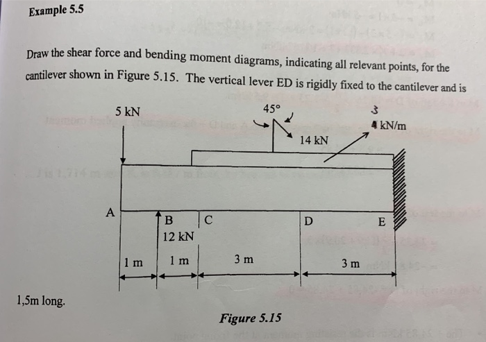
Solved Example 5.5 Draw the shear force and bending moment ...
Shear Force and Bending Moment - Materials - Engineering ...

Draw the shear force and bending moment diagrams for the beam ...
Mechanics of Materials Chapter 4 Shear and Moment In Beams
How can shear force be same throughout a cantilever beam with ...
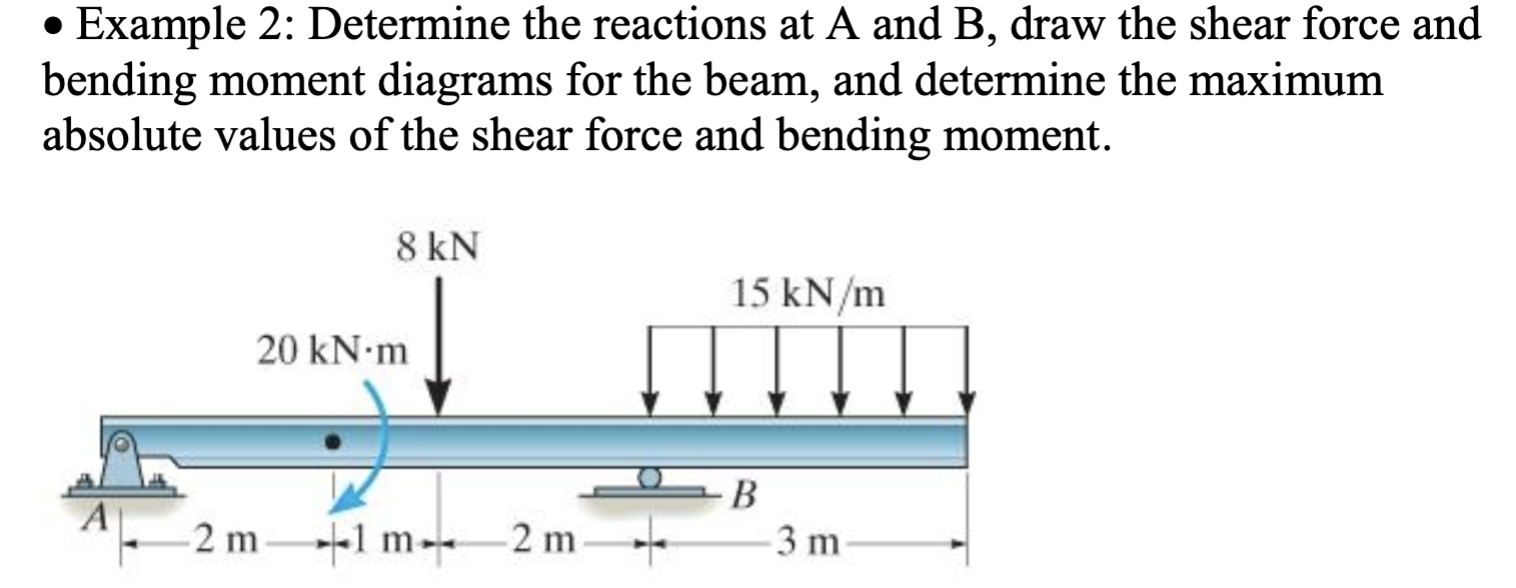
Solved • Example 2: Determine the reactions at A and B, draw ...
DE-12: Lesson 19. SOLVED EXAMPLES BASED ON SHEAR FORCE AND ...

Draw the complete shear force and bending moment diagrams for ...

Statics eBook: Shear, Moment and Load Relations

Shear force and bending moment diagrams example #1: single point load
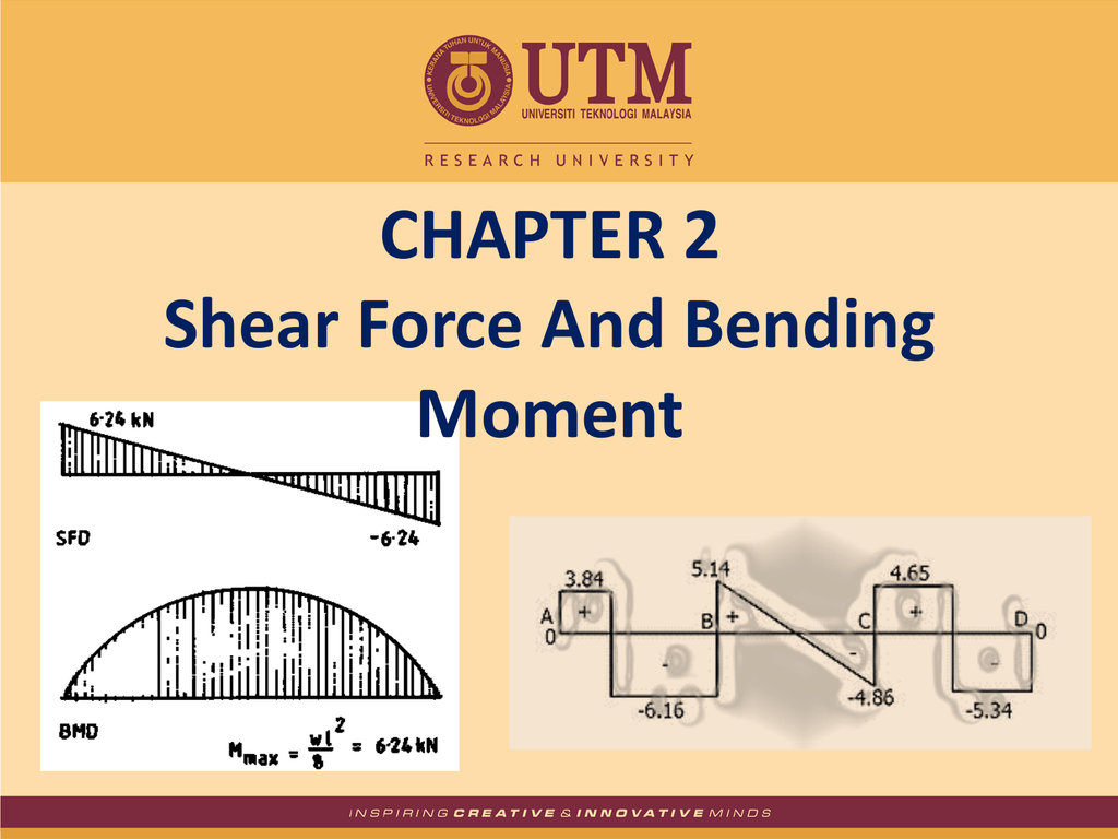
CHAPTER 2 Shear Force And Bending Moment

Cantilever Beam Shear Force And Bending Moment Diagram ...
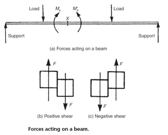
What is shear force and bending moment and why do we need to ...

BENDING MOMENTS AND SHEARING FORCES IN BEAMS - ppt download

Bending Moment Diagram - an overview | ScienceDirect Topics
Beam Analysis - Beam with uniformly distributed load(UDL ...
Solved Draw the shear force diagrams and the bending moment ...
Shear Force and Bending Moment Diagrams SFD BMD
Shear force and bending moment diagram practice problem #6
6.2 Shear/Moment Diagrams – Engineering Mechanics: Statics

Draw Shear Force And Bending Moment Diagram For Cantilever ...

Shear and moment diagram - Wikipedia
Theory | C5.3 Shear Force and Bending Moment Diagrams | Statics

How to Calculate and Draw Shear and Bending Moment Diagrams ...
The Ultimate Guide to Shear and Moment Diagrams ...
shear force and bending moment diagram - ppt download

Ultimate Guide to Shear Force and Bending Moment Diagrams ...
What Is Shear Force and Bending Moment? - Civil Lead

Shear force and bending moment diagram and examples - PIGSO ...
The Ultimate Guide to Shear and Moment Diagrams ...

Finding the Shear Force and Bending Moment Diagram for a Beam ...
Shear Force And Bending diagrams - Roy Mech

Shear force and bending moment diagram practice problem #3

14 meilleures idées sur genie civil | génie civil, lecture de ...
moment de force formule

The free-body diagram of the frame of Figures 2.29 and 2.30 ...
Shear Force and Bending moment Diagram
Module -4 Shear Force and Bending Moment Diagrams

Shear force and bending moment diagram practice problem #2

The Ultimate Guide to Shear and Moment Diagrams ...
0 Response to "44 shear force and bending moment diagram examples"
Post a Comment