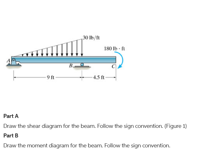
45 draw the shear diagram for the beam.
What are the steps for drawing a shear force diagram ... - Quora Therefore, I want to know where the maximum shear and moment occur along a beam, and what those values are. Now it should be said that many times a beam I am ...1 answer · 3 votes: Bending moment and shear force are related by the following relation Rate of change of ... Answered: Draw the shear diagram for the beam.… | bartleby First week only $4.99! arrow_forward. We've got the study and writing resources you need for your assignments. Start exploring! Engineering Mechanical Engineering Q&A Library Draw the shear diagram for the beam. Draw the moment diagram for the beam. Draw the shear diagram for the beam.
Shear Force and bending moment diagram for Simply ... Steps to draw Shear force and Bending moment diagrams. In SFD and BMD diagrams Shear force or Bending moment represents the ordinates, and the Length of the beam represents the abscissa. Consider the left or the right portion of the section. Add the forces (including reactions) normal to the beam on the one of the portion.

Draw the shear diagram for the beam.
Draw the shear and moment diagrams for the cantilevered beam 3. Take different beam sections and draw the free-body diagram of one of the segments. The shear force V and bending moment M should be shown acting in their positive sense, in accordance with the sign convention. 4. Calculate the shear force by summing forces perpendicular to the beam's axis. 5. Shear Force Diagram - How to Draw a SFD - mechGuru Start drawing shear force diagram from any of the extreme ends. Draw a vertical line of same length as the value of applied force at the point. If force acting on the point is downward then the vertical line should go downward or else upward. Draw the shear and moment diagrams for the beam shown in ... Support Reactions. The reactions at the supports have been determined and are shown on the free-body diagram of the beam, Fig. 6-7 d. Shear and Moment Functions. Since there is a discontinuity of distributed load and also a concentrated load at the beam's center, two regions of x must be considered in order to describe the shear and moment ...
Draw the shear diagram for the beam.. Answered: Draw the shear diagram of the beam… | bartleby Solution for Draw the shear diagram of the beam shown and determine the maximum shear. Incorrect diagram, no points. Show all necessary solutions. Mechanics Map - Shear and Moment Diagrams To create the shear force diagram, we will use the following process. Solve for all external forces acting on the body. Draw out a free body diagram of the body horizontally. Leave all distributed forces as distributed forces and do not replace them with the equivalent point load. Lined up below the free body diagram, draw a set of axes. How to Calculate and Draw Shear and Bending Moment Diagrams These instructions will help you to calculate and draw shear and bending moment diagram, as well as draw the resulting deflection. Knowing how to calculate and draw these diagrams are important for any engineer that deals with any type of structure because it is critical to know where large amounts of loads and bending are taking place on a beam so that you can make sure your structure can ... Shear and Moment Diagrams | Strength of Materials Review ... Shear and Moment Diagrams Consider a simple beam shown of length L that carries a uniform load of w (N/m) throughout its length and is held in equilibrium by reactions R 1 and R 2. Assume that the beam is cut at point C a distance of x from he left support and the portion of the beam to the right of C be removed.
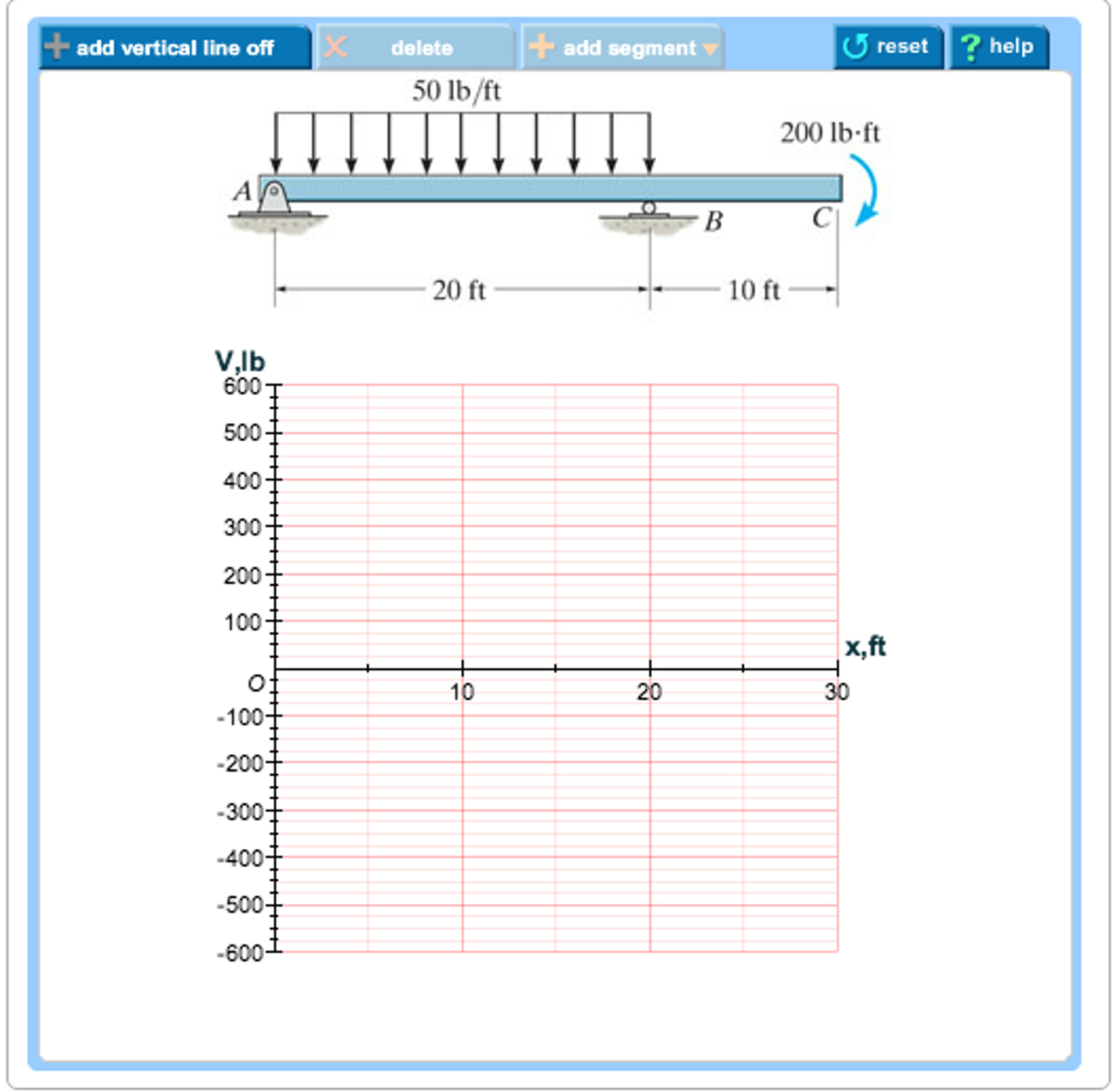
[Solved] For the beam and loading shown draw the shear and ... Are you looking for the beam and loading shown draw the shear and bending moment diagrams? then you are at the right place on the web. Beams come with different kinds and different types of loading on them. Hence, Submit your questio n and get solved within a few hours. Draw the shear diagram for the compound beam which is pin ... The compound beam is fixed at A. pin connected at B and supported by a roller at C. (Figure 1) PartA Draw the shear diagram for the beam Click on "add vertical line off" to add discontinuity lines. Then click on "add segment" button to add functions... The Ultimate Guide to Shear and Moment Diagrams You will be fully competent in drawing shear force and bending moment diagrams for statically determinate beams and ...23 Jul 2021 · Uploaded by DegreeTutors Solved Draw the shear diagram for the beam. Draw the ... Draw the shear diagram for the beam. Draw the moment diagram for the beam. Who are the experts? Experts are tested by Chegg as specialists in their subject area. We review their content and use your feedback to keep the quality high. Transcribed image text: Draw the shear diagram for the beam. Draw the moment diagram for the beam.
Draw the shear and moment diagrams for the overhang beam ... Shear Diagram. The shear of −2 kN at end A of the beam is plotted at x = 0, Fig. 6-16 c . The slopes are determined from the loading and from this the shear diagram is constructed, as indicated in the figure. In particular, notice the positive jump of 10 kN at x = 4 m due to the force B_y, as indicated in the figure. Moment Diagram. Draw The Shear Diagram For Cantilever Beam - The Best ... Draw Your Shear Force And Bending Moment Diagrams Required For Civil Engg By In132 Fiverr. Shear Force Bending Moment Diagram Of Cantilever Beam Exles Ering Intro. A Cantilever Beam Is Subjected To Various Lo As Shown In Figure Draw The Shear Force Diagram And Bending Moment For Ethiotutors. Solved Draw The Shear Force Diagram And Ben. Mechanics of Materials Chapter 4 Shear and Moment In Beams It is visually desirable to draw the V-diagram below the FBD of the entire beam, and then draw the M-diagrambelow theV-diagram. The bending moment and shear force diagrams of the beam are composites of the Vand Mdiagrams of the segments. These diagrams are usually discontinuous, or have discontinuous slopes. PDF Shear and Moment Diagrams - Memphis procedure for constructing the shear and moment diagrams for a beam. 2. To construct the shear diagram, first, establish the V and x axes and plot the value of the shear at each end of the beam. Shear and Moment Diagrams Procedure for analysis-the following is a procedure for constructing the shear and moment diagrams for a beam.
Draw the shear diagram and the moment diagram for the beam ...
PDF Third Edition LECTURE BEAMS: SHEAR AND MOMENT DIAGRAMS ... 2 LECTURE 13. BEAMS: SHEAR AND MOMENT DIAGRAMS (GRAPHICAL) (5.3) Slide No. 2 ENES 220 ©Assakkaf Example 8 (cont'd) A free-body diagram for the beam is shown Fig. 17. The reactions shown on the
The Ultimate Guide to Shear and Moment Diagrams ...
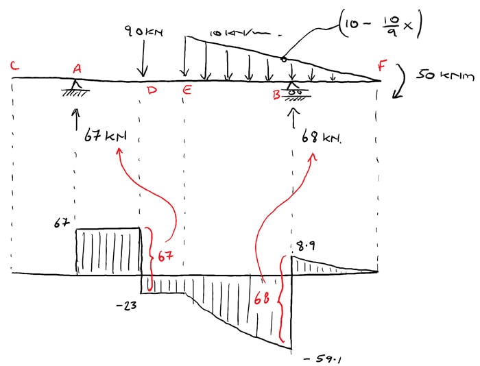
Medium To draw shear force diagram, first find value of shear force at point C,B and A. PROBLEM 6 120 W BON For the beam and loading shown, (a) draw the shear and bending-moment diagrams, (6) detcrminc the maximum absolute values of the shear and bending moment, 90 mm 100 mm Problem 1: Draw the shear force and bending moment diagram for the beam shown ...

Determine Reactions Draw Shear Bending Moment Diagrams Beams ...
Draw the Shear and Moment diagrams for the beam- With ... 1) Calculate the shear force and bending moment for the beam subjected to concentrated load as shown in the figure. Also, draw the shear force diagram (SFD) and the bending moment diagram (BMD). Solution; Free body diagram of the given figure, Taking moment about point B, R Ay x 4 - 20 x 2 = 0. 4 R Ay = 40.
Shear Load and Bending Moment Diagrams
Solved Draw the shear diagram for the beam. Assume that w ... Draw the shear diagram for the beam. Assume that w 0 =10kip/ft , and L=18ft Draw the moment diagram for the; Question: Draw the shear diagram for the beam. Assume that w 0 =10kip/ft , and L=18ft Draw the moment diagram for the
A Practical Graphical Approach for Drawing Shear Force and ...
Draw the shear and bending moment diagrams for the beam ... The shear force diagram for the beam is as below: The shear force and bending moment values at different locations of the beam are calculated. The shear force diagram and bending moment diagrams are is drawn by plotting the beam length along the x -axis and magnitudes of the shear force and bending moments along the y -axis. Step 4 of 13 5.7.a)
Solved Draw the shear diagram for the beam. Draw the | Chegg.com
Draw the shear and moment diagrams for the cantilever beam ... Draw the shear and moment diagrams for the cantilever beam in Fig. 6-15 a . Step-by-Step Report Solution Verified Solution Support Reactions. The support reactions at the fixed support B are shown in Fig. 6-15b. Shear Diagram. The shear at end A is −2 kN −2kN. This value is plotted at x = 0 x = 0, Fig. 6-15 c .
How to Draw Moment Diagrams | ReviewCivilPE
Shear force and bending moment diagram - SlideShare Draw shear force and bending moment diagrams [SFD and BMD] for beam. Also determine maximum hogging bending moment. 30N/m 4m [Ans: Max. Hogging bending moment = 735 kNm] Exercise Problems 4m3m VM-79 80. 5kN 8. A cantilever beam of span 6m is subjected to three point loads at 1/3rd points as shown in the Fig. given below. Draw SFD and BMD for ...

Draw shear and bending diagram for the beam given in the ...
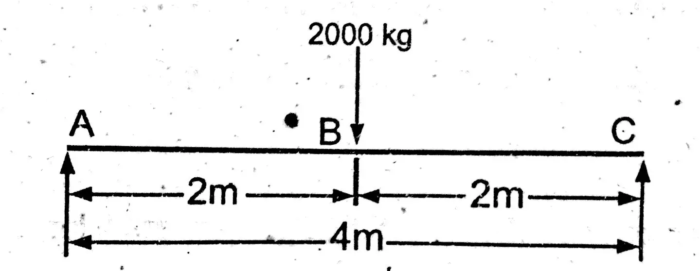
How to Draw Shear Force & Bending Moment Diagram | Simply ... Draw shear force and bending moment diagram of simply supported beam carrying point load. As shown in figure below. Solution First find reactions of simply supported beam. Both of the reactions will be equal. Since, beam is symmetrical. i.e., R1 = R2 = W/2 = 1000 kg. Now find value of shear force at point A, B and C.
Chapter 4: Internal Forces in Beams and Frames” in ...
PDF A Practical Graphical Approach for Drawing Shear Force and ... drawing the S/B diagrams. [1,2]The method of sections can be used to determine fully the shear force and bending moment at any cross-section of beams and to draw the S/B diagrams. When there are several external forces on a beam, the beam must be divided into several segments. The method of sections will be used repeatedly in each segment.
The Ultimate Guide to Shear and Moment Diagrams ...
draw the shear diagram for the beam chegg Draw Shear Force Diagrams For The Overhanging Beam Mechanical Ering Calculations for shear force and bending moment diagram overhanging beam express the internal shear and moment in terms of x then draw diagrams for overhanging beam study shear force and bending moment diagrams sfd bmd solved draw the shear and moment diagrams …
Hibbeler R.C. Structural Analysis
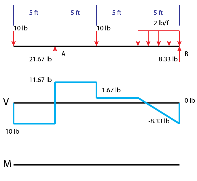
How to Draw Shear Diagrams | ReviewCivilPE The beam is 20ft long divided into 5 foot sections. Shear diagrams always begin and end at zero, with all of the forces on the member shown in between. Starting from the left, the first force you come across is the 10 lb downward force at the left end. This is the first point of data, draw a line from zero to negative 10.
Answered: Draw the shear diagram for the beam.… | bartleby
329 6–1. Draw the shear and moment diagrams for the shaft ... Draw the shear and moment diagrams for the beam. 2 m. 3 m. 10 kN. 8 kN. 15 kNm. 6–6. Draw the shear and moment diagrams for the overhang beam.143 pages

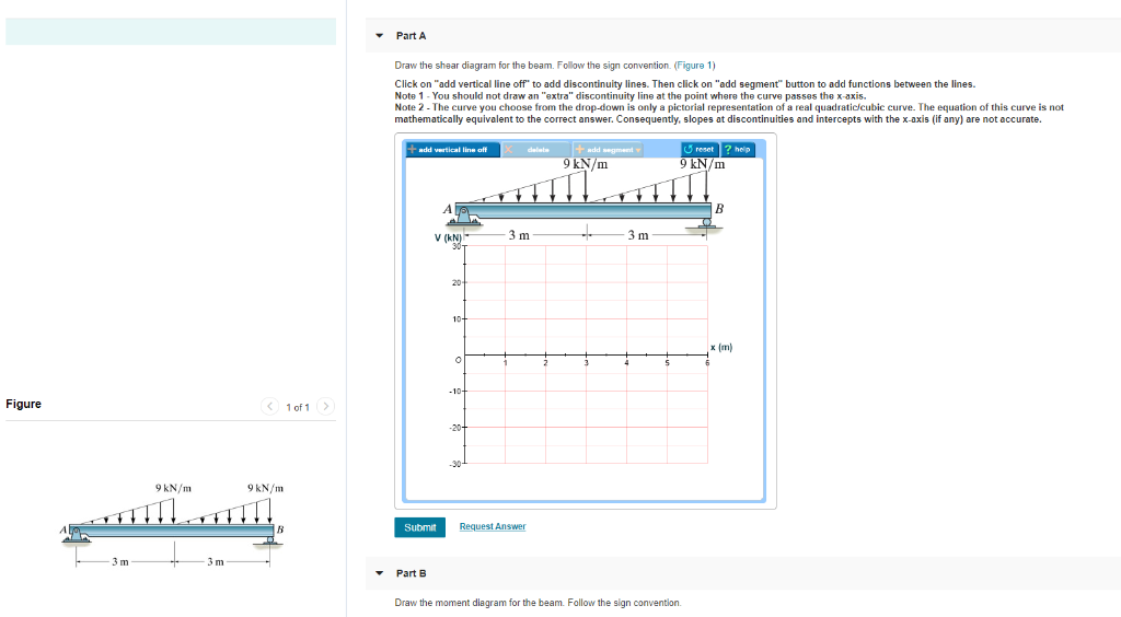
Part A Draw the shear diagram for the beam. Part B Draw the ...
Draw the shear and moment diagrams for the beams shown below Draw shear force and bending moment diagrams for the beam. Submit on Moodle as a pdf 30K W 600 ITE 3k wo 1200 lb 10 R BR 10 R BR>k on V M M Jul 31, 2019 · Great explanation for drawing the shear and moment diagrams for the beam draw the shear and moment diagrams for the beam, Slides for Mechanics of Materials. 250 lb 250 lb 150 411.

How to Calculate and Draw Shear and Bending Moment Diagrams ...
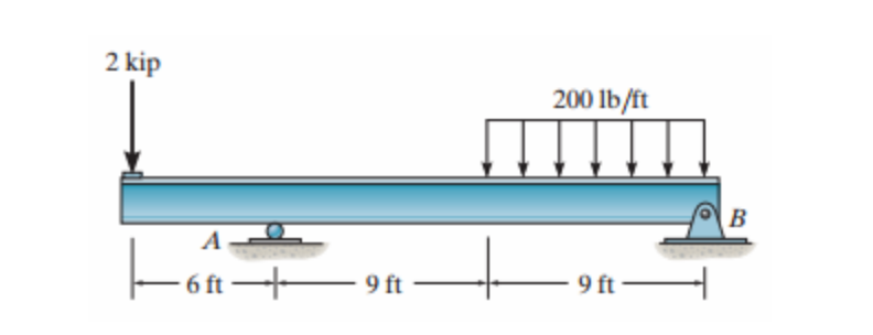
Solved a) Draw the shear diagram for the beam. b) Draw ... a) Draw the shear diagram for the beam. b) Draw the moment diagram for the beam. Part C. Determine the shear throughout the beam as a functions of x, where 0≤x<6ft. Express your answer in terms of x. Part D. Determine the moment throughout the beam as a functions of x, where 0≤x<6ft. Express your answer in terms of x. Part E

Draw the shear and moment diagram for the beam and loading ...
Draw The Shear And Moment Diagrams For The Overhang Beam. Shear and Moment Diagrams Procedure for analysis - the following is a procedure for constructing the shear and moment diagrams for a beam. The change in the shear force is equal to the area under the distributed loading. If the distributed loading is a curve of degree n, the shear will be a curve of degree n+1.
Calculations for Shear Force and Bending Moment diagram for ...
Draw the shear and moment diagrams for the beam shown in ... Support Reactions. The reactions at the supports have been determined and are shown on the free-body diagram of the beam, Fig. 6-7 d. Shear and Moment Functions. Since there is a discontinuity of distributed load and also a concentrated load at the beam's center, two regions of x must be considered in order to describe the shear and moment ...

Mechanics Map - Shear and Moment Diagrams
Shear Force Diagram - How to Draw a SFD - mechGuru Start drawing shear force diagram from any of the extreme ends. Draw a vertical line of same length as the value of applied force at the point. If force acting on the point is downward then the vertical line should go downward or else upward.

Drawing Shear Force, Bending Moment Diagram » File Exchange ...
Draw the shear and moment diagrams for the cantilevered beam 3. Take different beam sections and draw the free-body diagram of one of the segments. The shear force V and bending moment M should be shown acting in their positive sense, in accordance with the sign convention. 4. Calculate the shear force by summing forces perpendicular to the beam's axis. 5.
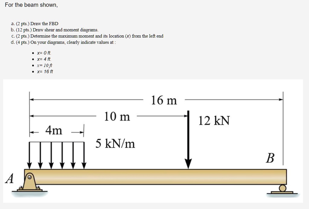
SOLVED:For the beam shown, (2 pts ) Draw the FBD b. (12 pts ...
How To Draw Shear Force And Bending Moment Diagram In Case Of ...
Draw the shear diagram for the beam - Home Work Help - Learn ...
How to Draw Shear Force & Bending Moment Diagram | Simply ...
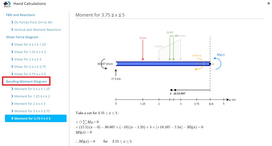
How to Calculate Bending Moment Diagram? | SkyCiv

Drawing Shear and Moment Diagrams for Beam
Shear Diagram - Beam with 3 supports | Physics Forums
Draw the shear diagram for the beam. - StudentShare

Draw the shear and moment diagrams for the overhanging beam ...
Solved) : Part Draw Shear Diagram Beam Follow Sign Convention ...
Structural Axial, Shear and Bending Moments
How to draw bending moment and shear force diagram for beams ...

Statics 7.61 - Draw the shear and moment diagrams for the beam.

05.2-1 Shear and moment diagrams graphical method - EXAMPLE
Draw the shear diagram for the beam. Draw the moment diagram ...

Pin on U-BEAMS STANDARD SIZES
329 6–1. Draw the shear and moment diagrams for the shaft ...
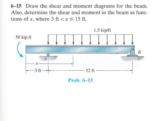
Solved) : Draw Shear Moment Diagrams Beam Also Determine ...

How to draw bending moment and shear force diagram for beams ...

Moment Diagrams Constructed by the Method of Superposition ...
Mechanics of Materials Chapter 4 Shear and Moment In Beams

For the figure below, draw the shear and moment diagrams for ...
Answered: Draw the shear diagram for the beam.… | bartleby

Solved) - Part A Draw the shear diagram for the beam Part B ...

Shear and moment diagram - Wikipedia
Chapter 4: Internal Forces in Beams and Frames” in ...
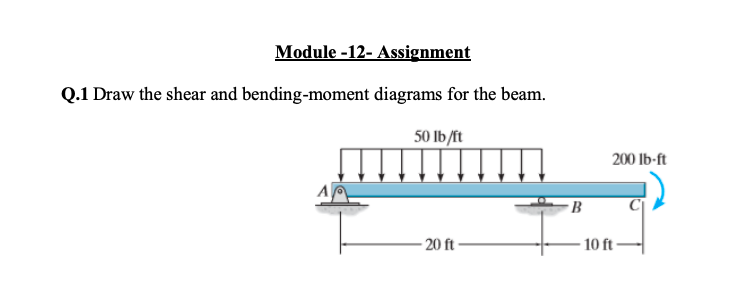
Solved) : Module 12 Assignment Q1 Draw Shear Bending Moment ...
0 Response to "45 draw the shear diagram for the beam."
Post a Comment