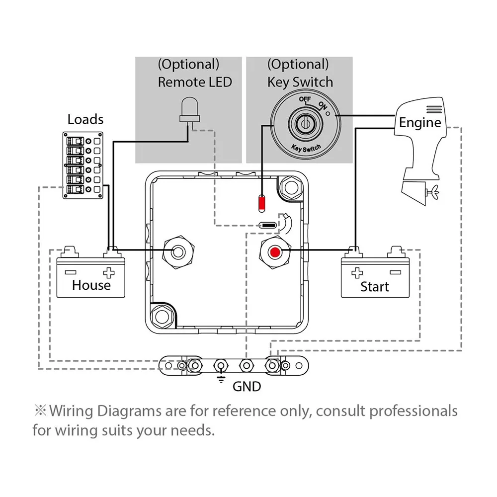
41 automatic charging relay wiring diagram
Wiring & diagram Info: Automatic Battery Charger Wiring ... Automatic Battery Charger Circuit Diagram The schema has been basically designed for a car battery (about 40 Ah rating), which could be used for lighting two 40W tube lights. The schema includes Schmitt trigger relay driver,float charger,and battery voltage monitor sections. The Schmitt trigger is incorporated to avoid relay chattering. automatic charging relay wiring diagram - Wiring Diagram ... Feb 22, 2016 · Battery Charger Wiring Diagram Management System Relay Png 1472x1269px Ampere Area Blue Sea Systems Auto Charging Relay Vsr M Acr Pn 7601 Relays And Solenoids Bottom Line Isle Of Man 12v 140amp Voltage Sensitive Relay Double Battery Automatic Charging Dual Smart Isolator In Tashkent
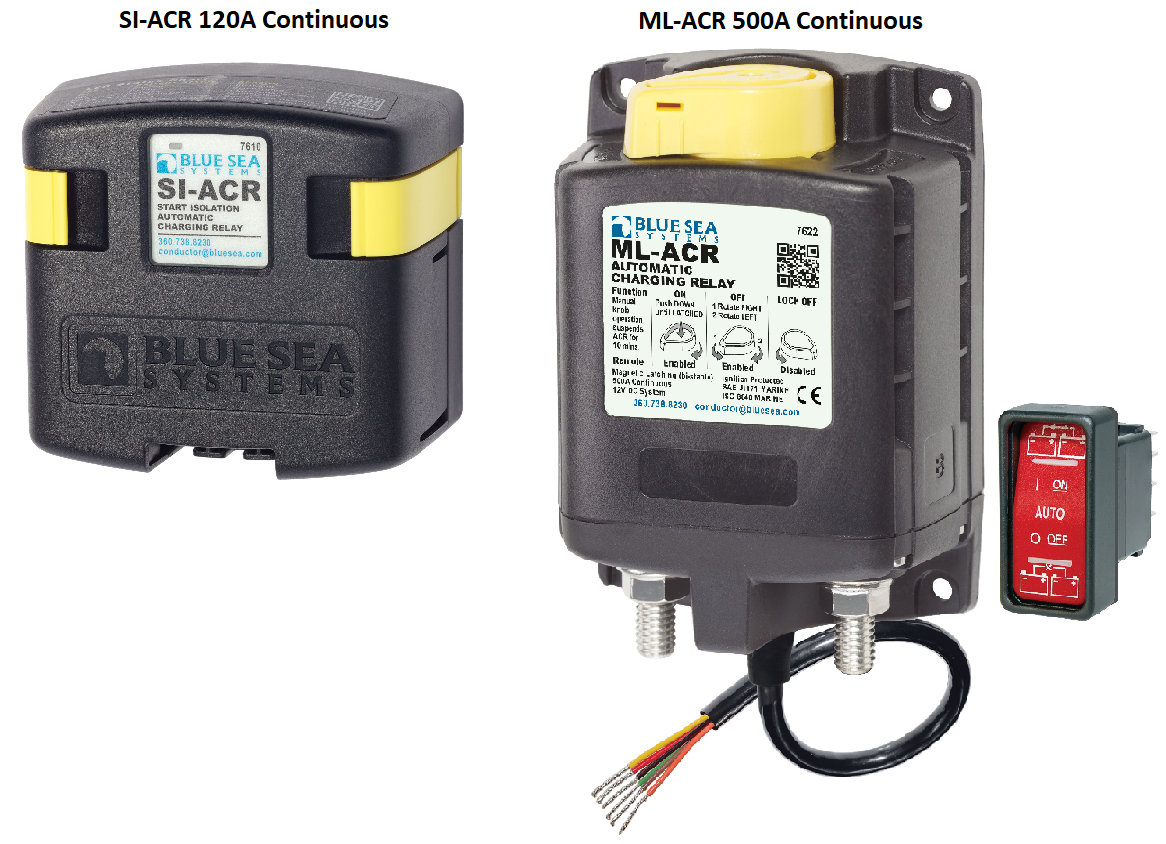
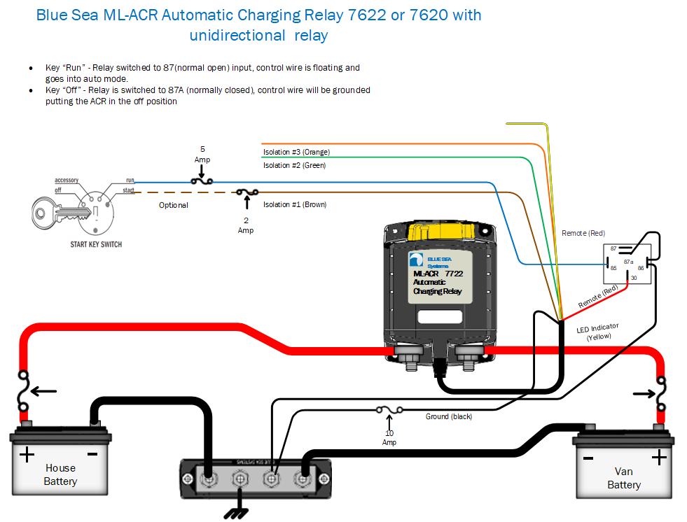
ML-ACR Automatic Charging Relay Manual 12V - Blue Sea ML-ACR Automatic Charging Relay Manual 12V Meets the following Regulatory Specifications Remote Battery Management and ACR SubSystem The ML-ACR (Automatic Charging Relay) and ML-RBS (Remote Battery Switch), when paired, offer complete battery management of large battery banks with the push of a button.

Automatic charging relay wiring diagram
Alternator Voltage Regulation 101 (with Wiring Diagrams ... All modern charging systems use some form of regulation that's purely electronic. Wiring Diagram (External Electromechanical Voltage Regulator) Refer to the simple diagram below for systems with an external electromechanical voltage regulator. A typical alternator wiring diagram with an external electromechanical voltage regulator. Installing a Automatic Charging Relay (ACR) - Practical ... Wiring Diagram: Checking the operation of the VSR An LED indicator on the front of the ACR shows its status. You can check the operation of the unit with a multimeter. With the engine off, the house battery is 12.39V and the start battery 12.65. With the engine running, you can see that both batteries are charging at 14.3V. Automatic Charging Relay Wiring Diagram Download - Wiring ... Apr 11, 2018 · automatic charging relay wiring diagram – Just What’s Wiring Diagram? A wiring diagram is a sort of schematic which uses abstract photographic icons to reveal all the affiliations of components in a system.
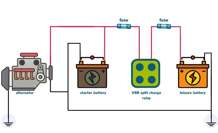
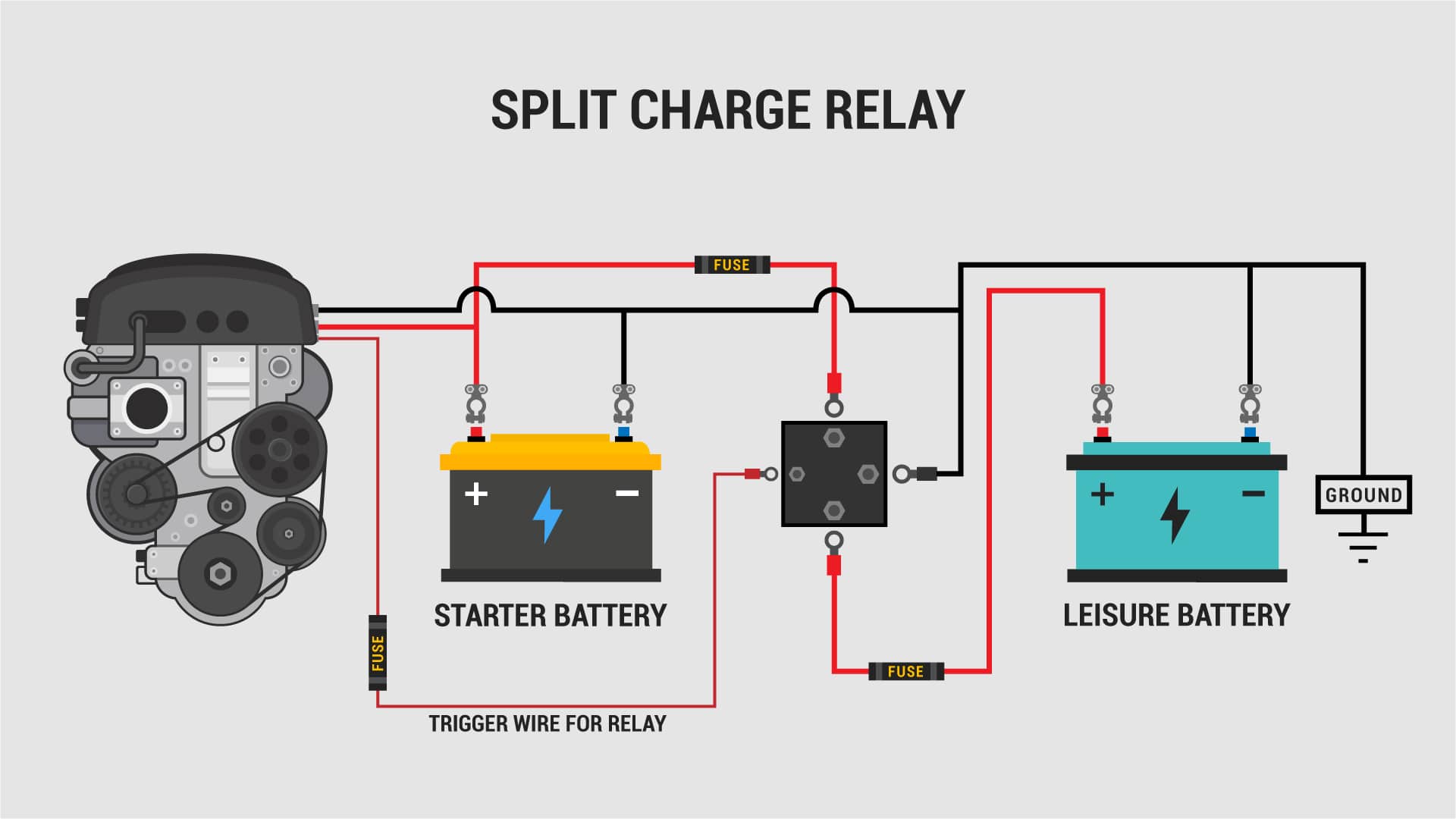
Automatic charging relay wiring diagram. Split Charge Relay Wiring Diagram - 36guide-ikusei.net Split charge relay and system frequently asked questions pertaining to voltage sensing relay wiring diagram, image size 794 x 560 px, and to view image details please click the image. Sensing is automatic and does not require the use of a separate lead from the ignition switch. Alternator Wiring Diagram: A Complete Tutorial | EdrawMax This is a three-wire alternating wiring diagram showing the connections between the different components of a circuit. The circuit comprises three main wires: battery positive cable, voltage sensing wire, and ignition wire. The ignition input wire is attached to the engine. Ml-Acr Automatic Charging Relay With Manual Control - 12V ... Ml-Acr Automatic Charging Relay With Manual Control - 12V Dc 500A - Auto Relay Wiring Diagram Wiring Diagram arrives with a number of easy to stick to Wiring Diagram Instructions. It's meant to help all the typical consumer in developing a suitable method. These guidelines will likely be easy to comprehend and implement. Durite Voltage Sensitive Relay Wiring Diagram - IOT Wiring ... Durite Voltage Sensitive Relay Wiring Diagram. By ... Split charging guide for campervans kits diagrams installation tips campervan a helpful ilrated vanlife adventure 0 727 33 durite 12vdc voltage sensitive charge relay electrics glossaries search 12v 140amp 8m kit ready made mega van mats 200a programmable 43 35 make break isolator smart off ...
3.Starter Relay. The starter relay is another switch that is used to control the starting circuit. In the start control circuit, the relay is connected in series with the battery to shorten the transmission of the large current cable length. 1.Car Starter Wiring Diagram - Non-Relay Control Type Battery Charger Circuit Diagram With Auto Cut Off Pdf - U ... As the battery charges the voltage across A point. Battery charger circuit diagram with auto cut off pdf.For an Automatic ONOFF Function. For charging these batteries you can use the circuit explained in the following article just make sure to use a current thats 50 less than the mAh value. 11 Full PDFs related to this paper. PDF Technical Brief—Automatic Charging Relay (ACR) Explained ML-Series Heavy Duty Automatic Charging Relay (ACR) Diagnostic Flowchart SYMPTOMTHE ACR WILL NOT COMBINE BATTERIES. CONNECT GROUND WIRE AS DESCRIBED and restart MANUAL function check. ACR IS NOT FUNCTIONING PROPERLY. contact Blue Sea Systems. YES Does the ACR produce a "CLICK" sound? NO PROCEED TO STEP 2 (below) YES PDF How To Wire Alternator - Vintage Auto Garage 1. Where a ballast resistor is not used, connect the DA Plug long wire to the Coil + terminal as indicated by the dashed line. Omit wire between Starter Relay terminal I and Coil + terminal. 2. Diode is built into the DA plug long wire. 3. Starter relay shown wired for Direct Drive Starter Motor. 4.
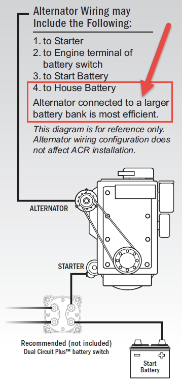
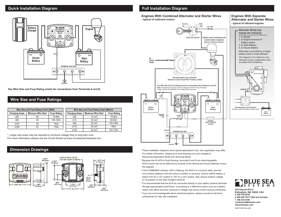
6 volt battery charger circuit diagram - Wiring Diagram ... Car Battery 6v Or 12v Charger Circuit Diagram And Instructions. Battery charger circuit for 12v 6v 5 best 4ah automatic 6 volt off 69 4 5ah using with auto diagram indicator nimh 12 lead acid solar lm317 adjule cur 12a smart car or an 24 gel cell fast 9v nicd 1 3ah make cheap results page about 2v 24v 100ah charge in automobile low cutoff batteries searching circuits electronic charging many ... Automatic Charging Relay Installation - Boating Mag Select the Wire Size Boating Magazine 1. Select the Wire Size Make sure you use marine wire and fuses sized to handle the engine's alternator output and starting requirements. Check the owner's manual to determine the amperage output and draw, and then go to boatingmag.com/amp-draw. Plan the Layout Boating Magazine 2. Plan the Layout Charging System & Wiring Diagram - YouTube Charging System & Wiring DiagramAmazon Printed Bookshttps:// Kindle Editionhttp:// ... PDF Installation Instructions Features and Specifications for ... This diagram is for reference only. Alternator wiring configuration does not affect ACR installation. Engines With Separate Alternator and Starter Wires - typical of inboard engines Recommended (not included) Dual Circuit Plus™ battery switch SI-ACR AUTOMATIC CHARGING RELAY with START ISOLATION Accessories Legend DC Positive DC Negative ...
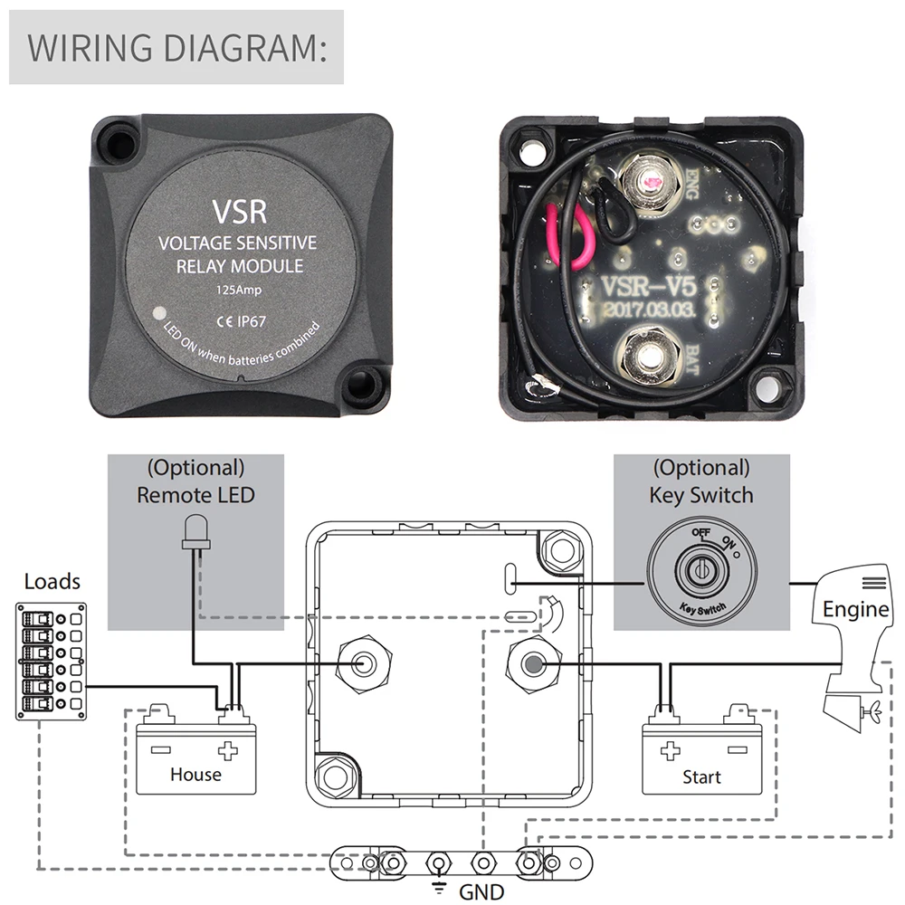
Vsr Relay Wiring Diagram Vsr Relay Wiring Diagram. Jul 12, A VSR (voltage sensitive relay) is perfect for dual battery systems. This diagram shows how you can use a dual sense VSR for charging both. Now, thanks to BEP's unique VSR (Voltage Sensitive Relay) boat owners can enjoy A: It is vital to follow the wiring installation diagram which shows correct.
DIY AUTOMATIC SOLAR CHARGE CONTROLLER : 7 Steps (with ... Step 4: Wiring. The Fig show the wiring diagram of the SSC. First connect the +ve from the solar panel to the centre pole of the relay then connect a red wire from battery to N.O of the relay. connect the -ve wire from the solar panel to the -ve of the circuit then connect the battery's-ve to the circuit. Ask Question.
Isolation Relay Wiring Diagram - justussocializing.org Automatic Charging Relay Wiring Diagram Collection Collection Automatic Charging Relay Wiring Diagram Download Tags: alco fr110 isolation relay, isolation relay for a e30b4d015aba, isolation relay function, isolation relay tractor, isolation relay wiring diagrams
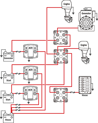
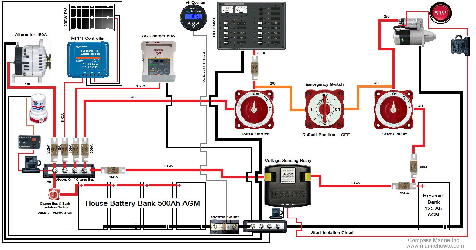
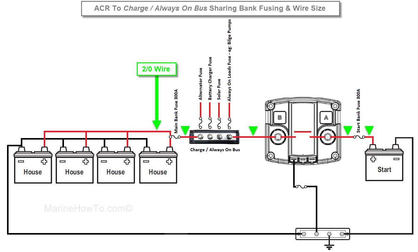
Making Sense of Automatic Charging Relays - Marine How To This image is intentionally over-simplified to show relay closed parameters and relay installation wiring and location. If you notice there are no battery switches, chargers, alternators etc. shown in this drawing. This is done purposely.
Automatic Charging Relay (ACR) Explained - Blue Sea Mar 20, 2009 · An ACR is intended to keep a load from discharging both of the batteries. How does an ACR work? An ACR senses when the voltage of either of the batteries rises to a level indicating that a charge source is active (13.0V for 2 minutes). The ACR′s contacts then connect and the ACR applies the charge to both batteries.
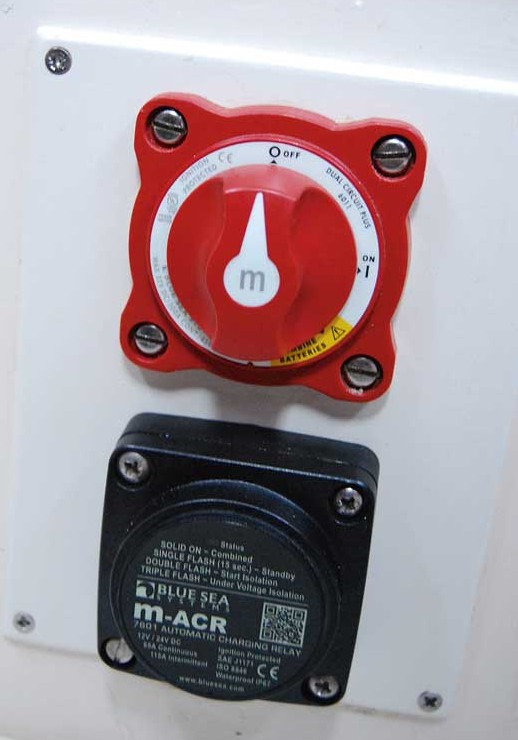
PDF Features and Specifications for M-ACR Automatic Charging ... Installation Instructions M-ACR Automatic Charging Relay 7601 425 Sequoia Drive Bellingham, WA 98226 USA p 360.738.8230 conductor@bluesea.com start accessory run off Dual Circuit Plus™ Battery Switch 6011 Included in Mini Add-A-Battery kit, recommended for 7601 m-ACR m-ACR 7601 START KEY SWITCH
Automatic Charging Relay Wiring Diagram Gallery - Wiring ... May 19, 2018 · automatic charging relay wiring diagram – What’s Wiring Diagram? A wiring diagram is a type of schematic which uses abstract pictorial symbols to show all of the interconnections of components in a very system.
Automatic Charging Relay Wiring Diagram Gallery ... Automatic Charging Relay Wiring Diagram Gallery Find this Pin and more on Feller's Electrical Stuff by Michael Feller. Electrical Panel Wiring Electrical Circuit Diagram Circuit Drawing Power Wheels Jeep Boat Wiring Switch House Train Map Diagram Design Safety Cover More information ... More information
Automatic Charging Relay Wiring Diagram - Free Wiring Diagram Automatic Charging Relay Wiring Diagram Assortment of automatic charging relay wiring diagram. A wiring diagram is a streamlined traditional photographic representation of an electric circuit. It reveals the elements of the circuit as streamlined shapes, as well as the power and also signal connections between the devices.
PDF Relays & Wiring 101 - Venture Rider Relays & Wiring 101 Basically, a relay is an electrically operated, remotely controlled switch. A simple electromagnetic relay is an adaptation of an electromagnet. It consists of a coil of wire surrounding a soft iron core, an iron yoke, which provides a low reluctance path for magnetic flux, a movable iron armature, and a set, or sets, of ...
Automatic Charging Relay Wiring Diagram Download - Wiring ... Apr 11, 2018 · automatic charging relay wiring diagram – Just What’s Wiring Diagram? A wiring diagram is a sort of schematic which uses abstract photographic icons to reveal all the affiliations of components in a system.
Installing a Automatic Charging Relay (ACR) - Practical ... Wiring Diagram: Checking the operation of the VSR An LED indicator on the front of the ACR shows its status. You can check the operation of the unit with a multimeter. With the engine off, the house battery is 12.39V and the start battery 12.65. With the engine running, you can see that both batteries are charging at 14.3V.
Alternator Voltage Regulation 101 (with Wiring Diagrams ... All modern charging systems use some form of regulation that's purely electronic. Wiring Diagram (External Electromechanical Voltage Regulator) Refer to the simple diagram below for systems with an external electromechanical voltage regulator. A typical alternator wiring diagram with an external electromechanical voltage regulator.













0 Response to "41 automatic charging relay wiring diagram"
Post a Comment