43 pulley system free body diagram
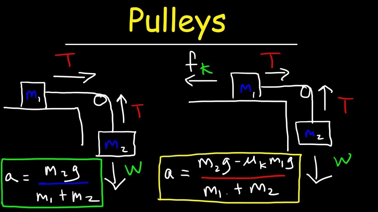
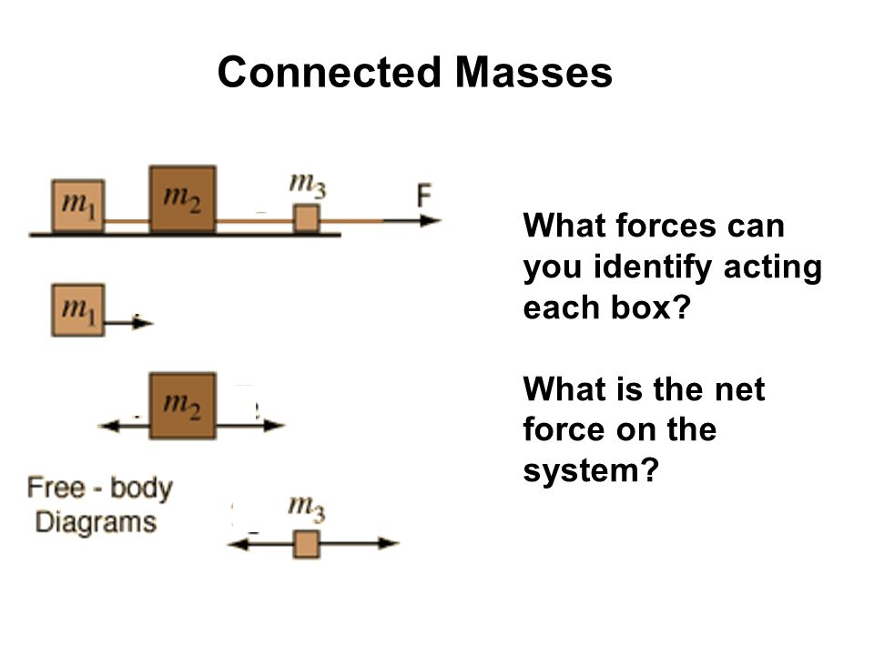
Basic Mechanics - Rice University From the perspective of a free-body diagram the compound pulley system could be replaced by tying two ropes to the load and pulling up on each with a force equal to the effort. The disadvantages of pulleys, in contrast to machines that use rigid objects to transfer force, are slipping and stretching. Two-Body Problems - Physics Classroom The free-body diagrams for each individual mass are shown below. Each object is experiencing a downward force of gravity - calculated as m 1 •g and m 2 •g respectively. Each object is also experiencing an upward tension force that pulls the two objects towards each other.
Free Body Diagram: Definition, Purpose, Examples, Steps ... In a Free-Body Diagram, the object is represented by its expression, usually a line, box, or a dot. The force vectors that act upon the object are represented by a straight arrow while moments are represented by a curved arrow around their respective axis as shown in the image below where a force is acting at B and a moment acts around A.

Pulley system free body diagram
5.7 Drawing Free-Body Diagrams | University Physics Volume 1 Figure 5.32 (a) The free-body diagram for isolated object A. (b) The free-body diagram for isolated object B. Comparing the two drawings, we see that friction acts in the opposite direction in the two figures. Because object A experiences a force that tends to pull it to the right, friction must act to the left. Because object B experiences a component of its weight that pulls it to the left ... Tension, String, Forces Problems with Solutions Several problems with solutions and detailed explanations on systems with strings, pulleys and inclined planes are presented. Free body diagrams of forces, forces expressed by their components and Newton's laws are used to solve these problems. Problems involving forces of friction and tension of strings and ropes are also included.. Problem 1 Pulley system free body diagram - YouTube About Press Copyright Contact us Creators Advertise Developers Terms Privacy Policy & Safety How YouTube works Test new features Press Copyright Contact us Creators ...
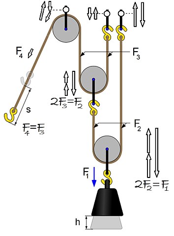
Pulley system free body diagram. PDF Mechanical Advantage with Pulleys - LEAPS Purpose: Assemble a pulley system to create a mechanical advantage. Draw free body diagrams and apply Newton's Law to accelerating systems. Materials: Assorted pulleys, neon-yellow string, accumulated physics expertise Procedure: 1. Assemble the following pulley system 1 2. Draw the free body diagrams for both M 1 and the bottom pulley in ... Statics eBook: Equilibrium & Free Body Diagrams The diagram on the left shows the pulley system with the external forces and with the elevator forces. The free-body diagram for pulley number 2 is shown on the left. Note that the free-body diagram for the pulley number 4 would be similar. Summing the forces in the vertical direction gives, PDF ENGR-1100 Introduction to Engineering Analysis FREE-BODY DIAGRAMS (Section 5.2) 2. Show all the external forces and couple moments. These typically include: a) applied loads, b) support reactions, and, c) the weight of the body. Idealized model Free-body diagram (FBD) 1. Draw an outlined shape. Imagine the body to be isolated or cut "free" from its constraints and draw its outlined shape. PDF 5-4 A System of Two Objects and a Pulley - WebAssign system of two objects and a pulley. Figure 5.7: Free-body diagrams if there is no friction. (a) The free-body diagram of the red box. (b) An appropriate coordinate system for the red box. (c) The free-body diagram of the red box, with force components aligned with the coordinate system. (d) and (e), a free-body diagram and coordinate system for ...
Pulley Free Body Diagram - Physics Forums fbd free body diagram pulley system statics Sep 20, 2015 #1 Alison A. 86 2 Homework Statement A collar with a pulley slides on a frictionless vertical bar GH. A string A B C D is wrapped around, where portion AB of the string is horizontal. A spring with 2.5 lb/in. stiffness is placed between the collar and point H. Free Body Diagram (how do you make free body ... - YouTube Making accurate free body diagrams for a system of blocks connected by string and pulleys is an important step towards writing the correct equations of motio... Free Body Diagrams, Tutorials with Examples and Explanations The free body diagram helps you understand and solve static and dynamic problem involving forces. It is a diagram including all forces acting on a given object without the other object in the system. You need to first understand all the forces acting on the object and then represent these force by arrows in the direction of the force to be drawn. What is Free Body Diagram in Physics - Definition, Purpose ... A free body diagram is a diagrammatic depiction of a single body or a subsystem of bodies that is separated from its surroundings and shows all of the forces operating on it. A free body diagram (force diagram, or FBD) is a graphical representation used in physics and engineering to illustrate the applied forces, moments, and consequent ...
(Get Answer) - 2. (3 pts) Draw a free-body diagram for the ... 2. (3 pts) Draw a free-body diagram for the force probe in all three pulley systems. Mark which forces are equal. 4 Procedure Part I: Pulleys 1. Fixed pulleys can be used to change the direction of a force. In Lab 3 we used two fixed pulleys to attach will use moveable pulleys attached to the object... Solved C. Torque and angular acceleration. 1. Draw an ... 1. Draw an extended free body diagram for the pulley and pulley AT hanger system (see the diagrams to the right) acceleration (but not at g), the linear acceleration is related to the angular acceleration byand torque is related to force by tr', we have. mass hanger 2. Remembering that the falling weight is undergoing 38 pulley system free body diagram - Diagram For You Free Body Diagram Pulley System - Web Information Jan 27, 2022 · Free body diagrams The mechanical advantage of a pulley system can be analysed using free body diagrams which balance the tension force in the rope with the force of gravity on the load. The free body diagram below shows the weight w and the tension t1 acting on the block. 2.972 How an Elevator Works - Massachusetts Institute of ... Free body diagram of the pulley system: The following analysis has been done for steady state (no acceleration )operation. The force on the driving pulley is equal to the difference of the two exerted tensions on each side. On one side, this force is equal to W e and on the other side, it is W c.
Physics 4.8 Free Body Diagrams (8 of 10) 3 Masses on a Table (With Friction)
Solved Use the free body diagram of the pulley (Figure 4 ... Use the free body diagram of the pulley (Figure 4) to answer the Pre-Lab Questions. 1. Draw a free body diagram for M1. 2. Draw a free body diagram for M2. 3. Apply Newton's 2nd Law to write the equations for M1 and M2. You should get two equations with Tension in the string, weight for each mass and accelerations for each mass (a1 and a2). 4.

Statics eBook: Equilibrium & Free Body Diagrams
Pulley in Physics - pulley tension problems with solution ... figure 1 - pulley setup We have to draw one free-body diagram (FBD) for the hanging cylinder and another for the cart. 1. Each subject is represented by a dot (labeled with the mass) in Figures 2 and 3. - Figure 2 shows the FBD of the cart. - Figure 3 represents the FBD of the cylinder. 2. Forces are drawn and labeled on each object.
File:Power Pulley FBD.jpg - Wikimedia Commons
5.7 Drawing Free-Body Diagrams - General Physics Using ... Figure 5.32 (a) The free-body diagram for isolated object A. (b) The free-body diagram for isolated object B. Comparing the two drawings, we see that friction acts in the opposite direction in the two figures. Because object A experiences a force that tends to pull it to the right, friction must act to the left. Because object B experiences a component of its weight that pulls it to the left ...

Jacobs Physics: Three masses connected over a pulley
PDF 4.3. Tension and Pulleys Pulleys: Demonstration 1. How might a pulley change tension? 2. What would the free-body diagram of the balance of forces be for a rope and a pulley: a. For the rope turned 90 degrees? b. For the rope turned 180 degrees? 3. Experiment!
Solved Draw the Free Body Diagram of the examined system and ...
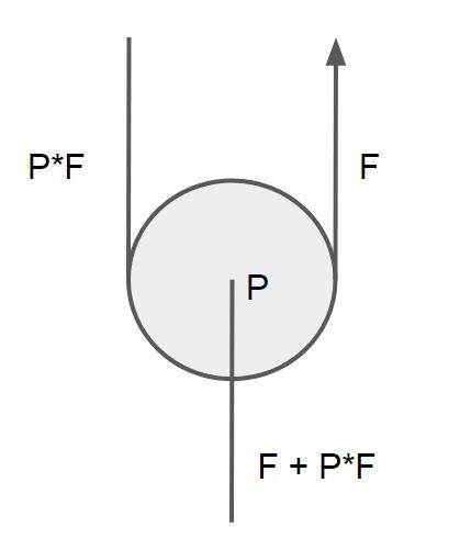
Types Of Pulley:Exhaustive Insights Free body diagram of Moveable pulley Working of moveable pulley When the free end of the pulley is pulled down, the pulley slide over the string and uplift the object, this pulley is beneficial if you are at a higher altitude and the object is below your level.
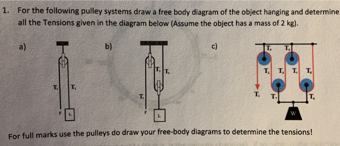
Solved 1. For the following pulley systems draw a free body ...
Free Body Diagram Pulley System - Web Information Free body diagram of a pulley. A free body diagram force diagram or FBD is a graphical representation used in physics and engineering to illustrate the applied forces moments and consequent. Draw the free body diagrams for both M 1 and the bottom pulley in equilibrium.
Pulley Physics Problem - Finding Acceleration and Tension Force
PDF Modeling Mechanical Systems - California State University ... • Establish inertial coordinate system • Identify and isolate discrete system elements (springs, dampers, masses) • Determine the minimum number of variables needed to uniquely define the configuration of system (subtract constraints from number of equations) • Free body diagram for each element

Engineering Mechanics - ppt download
PDF Physics Kinematics, Projectile Motion, Free-Body Diagrams ... pulley. Then they push safe out of the window. What is the safe's speed when it hits the truck? What is the force exerted on the truck by the safe? µ=.5 Rotational Motion 1. Draw a diagram of the object or objects that will be the system to be studied. 2. Draw a Free-body diagram for the object under consideration. 3.

Pulleys - Physics for K-12 - OpenStax CNX
PDF Activity 2.1.3 Free Body Diagrams Free Body Diagram Practice M1 M2 FBD of Mass 1: F T FBD of the movable pulley: W 1 W 2 + W pulley F T F T Tension Forces (F T ) are equal throughout the system. Create a FBD for the pulley system pictured below.
eNotes: Mechanical Engineering
PDF Physics 20 Lesson 18 Pulleys and Systems masses that are connected and accelerating together. Using the pulley system illustrated to the right below as an example, the basic method for discussed. As in Lessons 15, 16 and 17, the basic method is to draw a free body diagram of the forces involved, write an expression for the net force, and then solve for the acceleration. In a pulley ...
Two-Body Problems
Mathematical Models of Translating Mechanical Systems Example: System with Pulley (Solution 1: summing Torques) Develop a mathematical model in terms of the position x 2. Take the equilibrium position of x 1 and x 2 to be 0 when f a =0. Since the equilibrium position is defined to be zero we need not consider gravity in our model . Let's draw free body diagrams (one for x 1, x 2 and θ)
Cheap,pulley system diagram,www.oundlebespokeapartments.co.uk
Pulley system free body diagram - YouTube About Press Copyright Contact us Creators Advertise Developers Terms Privacy Policy & Safety How YouTube works Test new features Press Copyright Contact us Creators ...

Problem: Two masses on a pulley | Phyley
Tension, String, Forces Problems with Solutions Several problems with solutions and detailed explanations on systems with strings, pulleys and inclined planes are presented. Free body diagrams of forces, forces expressed by their components and Newton's laws are used to solve these problems. Problems involving forces of friction and tension of strings and ropes are also included.. Problem 1

newtonian mechanics - Resultant force on a system with two ...
5.7 Drawing Free-Body Diagrams | University Physics Volume 1 Figure 5.32 (a) The free-body diagram for isolated object A. (b) The free-body diagram for isolated object B. Comparing the two drawings, we see that friction acts in the opposite direction in the two figures. Because object A experiences a force that tends to pull it to the right, friction must act to the left. Because object B experiences a component of its weight that pulls it to the left ...

Part 4
Draw the F.B.D. (Free Body diagram) of two blocks | Physics ...
b) Draw a free-body diagram for the powered pulley | Chegg.com
Mechanical Advantage of 3 Pulley System - Engineering Stack ...

A pulley system — Collection of Solved Problems
newtonian mechanics - Interaction between an ideal pulley and ...
free body diagram for pulley
newtonian mechanics - Connected system - Physics Stack Exchange

Physics 4.8 Free Body Diagrams (2 of 10) The Atwood Machine ...

Fixed Pulley — Collection of Solved Problems

Solved C. Torque and angular acceleration. 1. Draw an | Chegg.com

Find the motion of mass, m, of the mass-pulley system when it ...
Pulley system analysis | RopeLab Online

Levers and Pulleys in Translating Mechanical Systems

eNotes: Mechanical Engineering
Two-Body Problems
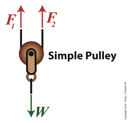
Using a Free Body Diagram to Understand Simple Pulleys ...

Pulleys - Physics for K-12 - OpenStax CNX

Statics eBook: Equilibrium & Free Body Diagrams

Pulleys - Physics for K-12 - OpenStax CNX

A mass M is held in place by an applied force F and a pulley ...
Force Systems accelerate together Combination Systems ...

Free Body Diagram (how do you make free body diagrams?) #6

Tension, String, Forces Problems with Solutions
pulleys

Free body diagrams | TikZ example

System of Pulleys — Mechanical Advantage Calculator ...
eNotes: Mechanical Engineering
pulley force,mobilibianco.it
0 Response to "43 pulley system free body diagram"
Post a Comment