44 3 wire coil diagram
2012 3.5 ecoboost wire diagram for coil packs. the wire ... 2012 3.5 ecoboost wire diagram for coil packs. the wire connectors all broke bought new ones and believe a few wires are - Answered by a verified Ford Mechanic Wiring Diagram 2 Humbuckers 3 Way Switch - U Wiring Wiring 2 humbuckers 1 vol tone 3 mini s diagram for humbucker way wire a single conductor madcomics switch blade flexible dual scheme two with one volume volumes tones golden age kit pickups pickup guitar coil split seymour duncan do it all hoagland custom tele les paul three crl lever stewmac push pull no diagrams archives. 2 Humbuckers 1 ...
Wiring the Coils in 3 Phases Axial Flux Generators : 3 ... Step 3: THE COMPLETE WIRING. THIS IS THE COMPLETE WIRING OF THE COILS. and the hard part to understand. Pay close attention to this and look at the DIAGRAMS. The beggining of the first coil in Phase 1 goes to the beggining terminal of Phase 1. The ending of the first coil in Phase 1 is soldered to beggining ot the second coil in Phase 1.

3 wire coil diagram
Coil-on-plug primary voltage and current (3-wire) Coil-on-plug primary voltage and current (3-wire) The purpose of this test is to examine the primary voltage and current within a 3 wire coil on plug unit. WARNING. This test involves measuring a potentially hazardous voltage. Please ensure you follow manufacturers' safety instructions and working practices and ensure the rated voltage for all ... Mercruiser Ignition Coil Wiring Diagram - Today Wiring ... Mercruiser Ignition Coil Wiring Diagram - Today Wiring Diagram - Mercruiser 4.3 Wiring Diagram Uploaded by Anna R. Higginbotham on Monday, February 11th, 2019 in category Wiring Diagram. See also Wiring Harness(Engine) - 1998 Mercruiser 4.3L [Alpha Efi] 4231017L1 - Mercruiser 4.3 Wiring Diagram from Wiring Diagram Topic. 3 Pickup Guitar Wiring Diagrams - GuitarElectronics.com Neck Coil Tap+Bridge Coil Tap 4. Neck Coil Tap+Middle 5. Neck Humbucker; 3 Single Coils. 3 Single Coils/5-Way Lever Switch/1 Volume/2 Tones-Typical Fender Stratocaster Wiring; 3 Single Coils/5-Way Lever Switch/1 Volume/2 Tones-1 Push-Pull for Neck+Bridge Option (7-Sound Strat) 3 Single Coils/5-Way Lever Switch/1(2) Volumes/2(1) Tone-1 Push-Pull ...
3 wire coil diagram. Coil Induction & Wiring Diagrams - YouTube Coil Induction & Wiring DiagramsAmazon Printed Bookshttps:// Kindle Editionhttp:// ... 3.5 Hp Briggs And Stratton Ignition Coil Wiring Diagram 3.5 Hp Briggs And Stratton Ignition Coil Wiring Diagram. I've done it to put a coil from a 5 HP on a HP a few times. Just have to get magneto wire pulled out of condenser post/spring. . Every ignition system is a simple LC tank circuit that wants to resonate at a specific. Aug 9, This is on a HP Briggs engine. Humbucker Wiring Diagram 3 Way Switch - Wiring World Outside coils of both humbuckers 3. Basic guitar wiring diagram with 2 humbuckers, 3-way lever switch, one volume and one tone control. 1 is for a bridge humbucker that splits to the north coil, which is the slug side. The first doesn't.IronGear Pickups - Wiring 2 x Humbuckers (4-Wire), 1 Vol, 2 Tone, 3-way toggle, No Coil Switching. Ignition System Wiring Diagram (1995 3.1L V6 Oldsmobile ... Ignition System Wiring Diagram (1995 3.1L V6 Oldsmobile Cutlass Supreme) This simplified ignition system wiring diagram applies to the following vehicles: 1995 3.1L V6 Oldsmobile Cutlass Supreme. Ignition coil packs. Crankshaft position (CKP) sensor (low resolution sensor). 24X Crankshaft position (CKP) sensor (high resolution sensor).
Ignition Coil Circuit Wiring Diagram (1999-2002 V8 ... Ignition Coil Circuit Wiring Diagram. 1999, 2000, 2001, 2002 4.8L, 5.3L, 6.0L V8 Chevrolet Silverado and GMC Sierra. Chevy 5.3 Ignition Coil Wiring Diagram - easywiring Chevy 5.3 ignition coil wiring diagram. Testing the a no start problem or a misfire due to an ignition system problem is not hard. Find chevrolet 5 3l 325 ignition coil wiring harnesses and get free shipping on orders over 99 at summit racing. Do s and don ts and precautions. Ignition system diagnostic manual download. Coil pack wiring diagram 1998 buick 3.8 - Fixya Buick General Motor 3800 V6 Engine Firing Order DIS IDI ignition timing 3.8 Buick Engine Coil Pack Firing Order Spark Plug Wire Location Which way do the spark plug wires go on & what cylinder is what?. For the Buick V6 231 3.8 liter turbocharged engine:. Answers!. Firing order: 1 - 6 - 5 - 4 - 3 - 2.. Two Wire & Three Wire Motor Control Circuit - Electrical A2Z A three wire control circuit uses momentary contact, start/stop stations, and a normally open seal in contact connected in parallel with the start button to maintain voltage to the coil. The set up for the three wire sire control circuit is different from the two wire operation because there are less components needed to operate the load.
4.3 Vortec Ignition Coil Wiring Diagram For Your Needs 4.3 Vortec Ignition Coil Wiring Diagram. Print the cabling diagram off plus use highlighters to be able to trace the signal. When you employ your finger or perhaps follow the circuit with your eyes, it may be easy to mistrace the circuit. One trick that I use is to print exactly the same wiring picture off twice. Difference Between 2 wire RTD, 3 wire RTD, and 4 wire RTD's The 3 wire circuit works by measuring the resistance between #1 & #2 (R 1+2) and subtracting the resistance between #2 & #3 (R 2+3) which leaves just the resistance of the RTD bulb (R b). This method assumes that wires 1,2 & 3 are all the same resistance Lindy Fralin Wiring Diagrams - Beautiful Guitar & Bass ... Position 1 = Bridge, Position 2 = Bridge + Neck, Position 3 = Neck, Position 4 = Neck Coil Split, Position 5 = Bridge Coil Split. View Diagram Gibson Les Paul Jr. Wiring Diagram Honda 3wire Ignition Coil Wiring Diagram Gx390 This manual . Wiring Diagrams keep out dust. A hot engine and exhaust system can ignite or melt .. IGNITION COIL. FUSE. it has a 4-pin wire connector that plugs into the coil but only uses 3 wires, red, Re: honda gx blown ignition coils [Re: 1 FMF] # It has a Honda GX with electric start and low oil alert. Here's a link to a wiring diagram for ...
Ignition Coil Plastic Harness is broke 2004 Sonata 2.7 ...
3 Wire Coil Pack Diagram : Haltech LS2 / LS7 Coils ... 3 Wire Coil Pack Diagram : Haltech LS2 / LS7 Coils - RX7Club.com - Mazda RX7 Forum : Check out this guide to oven wiring problems, and to finding those oven wiring diagrams that you need.. Weaken windings inside a coil eventually break, creating resistance for the sp. Learning to read and use wiring diagrams makes any of these repairs safer ...

3-Wire Alternator Regulator Diagram - Seaboard Marine
Briggs And Stratton Coil Wiring Diagram - Wiring Diagram 8 Hp Briggs And Stratton Coil Wiring Diagram | Wiring Diagram - Briggs And Stratton Coil Wiring Diagram. Wiring Diagram consists of several in depth illustrations that show the link of varied items. It consists of guidelines and diagrams for various varieties of wiring methods as well as other things like lights, home windows, and so forth.

Need help replacing HVAC condensor fan motor - 3 wire old to ...
Guitar Wiring Diagrams | 1 Humbucker+1 Single Coil Easy to read wiring diagrams for guitars & basses with 1 humbucker & one single coil pickup. Options for North/South coil tap, series/parallel & more.
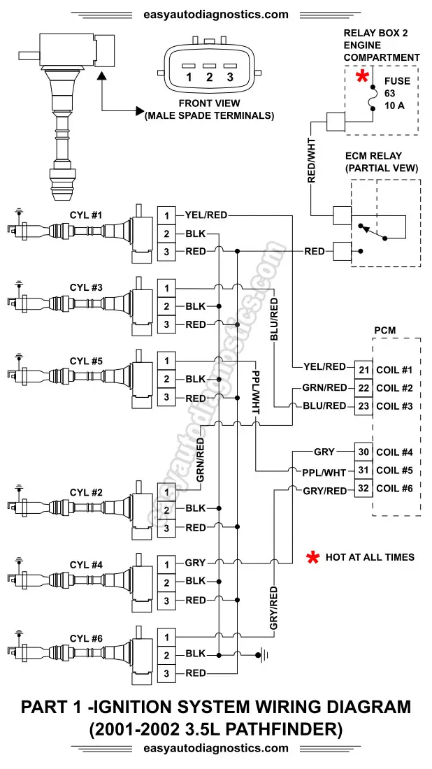
Part 1 -2001-2002 3.5L Nissan Pathfinder Ignition System ...
3 Phase Contactor 240v Coil Wiring Diagram - U Wiring Table 11 Ratings for 120240 V 3-Wire Single-Phase Dwelling Services101 Table 12 AWG and Metric Wire Data 102. Motor control wiring diagram. China Contactor 120v Coil Wiring Diagram Relay Switch 4 Pole. For 3 phase motor controlling diagram and procedure follow the below tips.
Is there a 240 circuit with only three wires? - Quora
Honda 3wire Ignition Coil Wiring Diagram Gx390 18.02.2019 18.02.2019 0 Comments on Honda 3wire Ignition Coil Wiring Diagram Gx390 The wiring diagram doesn't make any sense to me. positive battery cable terminal goes to BAT on switchwire from the fule solenoid on carburetor, has to has to go to groundIGN, has to go the two coils on engine, to kill engine.

How to Draw 3 Wire Alternator Wiring Diagram in EdrawMax
How to Wire a Motor Starter | Library.AutomationDirect.com Feb 11, 1999 · Full-voltage reversing 3-phase motors. This diagram is for 3-phase reversing motor control with 24 VDC control voltage. It uses two contactors, two auxiliary contact blocks, an overload relay, a mechanical interlock, two normally open start pushbuttons, a normally closed stop pushbutton, and a power supply with a fuse.
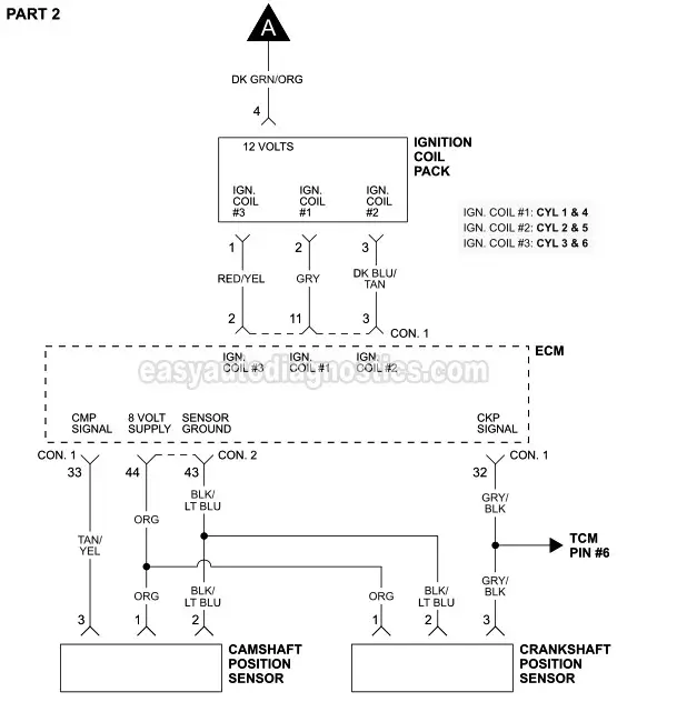
Ignition System Circuit Diagram (1996-1997 3.8L Chrysler ...
Guitar Wiring Diagrams | 3 Single Coil Pickups Guitar wiring diagram with three single coils, 5-way lever switch, 1(2) volume, 2(1) tones. Typical Strat style guitar with push/pull pot that converts the neck tone pot to a neck volume control to allow the neck to be blended in with the bridge and/or...

Need Help! Subaru Coil Pack Wiring Diagram - Auto Master X
How to Wire 12 Volt Coils - It Still Runs Older-model cars used the 12-volt ignition coils to provide power to the spark plugs. These coils had very simple wiring. They usually required only three wires: the spark plug wire, the power wire and the ignition switch wire. Ignition coils of this type are usually a little larger than a soda can and are heavy ...
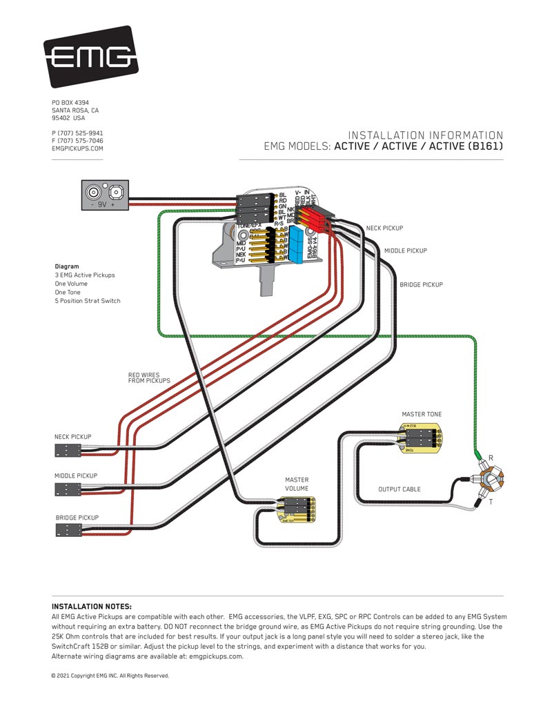
EMG Pickups / Top EMG Wiring Diagrams / Electric Guitar ...
SOLVED: Wiring diagram for 3 pin coil - Fixya Firing order diagram 1999 lumina. This diagram shows where your Spark Plugs/Cylinders Are. And the 3-Coils each coil supplies Voltage to 2- Plug Wires. Which i Show in the Center of above diagram ,#1 Plug wire goes to #1 on the Coil which in the Diagram is the Rear Coil and the farest back.

Tele® Standard 3-Way Switch
Coil Wiring Diagram - easywiring Coil wiring diagram. See the diagram under the section 4 ohm dual voice coil sub wiring diagram for the 1 ohm example. Wire nuts are supplied pre attached to leads 2 and 3 from factory. October 11 2020 at 10 46 pm. Through the thousand images on line regarding ignition coil condenser wiring diagram we all choices the top selections together ...

70 Awesome 3 Pin Relay Wiring Diagram | Relay, Wire ...
Coil On Plug Ignition: The Wired Differences 3 wire coils: PCM command pulse. Faulty coil identified . 2 coils from Maxima V-6 . coil on left fried . GOOD . BAD . GOOD . 4 . 6 . 4 . 4 wire coils . Toyota's version GM's version . 4 wire coil: Toyota version . The 4 wires are: 1. 12 volt power 2. Chassis Ground 3. PCM Command Pulse 4. "IGF" diagnostic
Coil Pack Wiring diagram needed 2007 Camry 2.4L | Toyota ...
Trembler coil - Wikipedia A trembler coil, buzz coil or vibrator coil is a type of high-voltage ignition coil used in the ignition system of early automobiles, most notably the Benz Patent-Motorwagen and the Ford Model T. Its distinguishing feature is a vibrating magnetically-activated contact called a trembler or interrupter , [3] [1] which breaks the primary current ...

OK, how do I wire a four pin GM coil to act like a regular ...
Part 1 -Testing and Troubleshooting 3 Wire COP Coils The Coil-On-Plug ignition coil has three wires coming out its connector. One of those wires (circuits) is the one that delivers 12 Volts to the coil. Usually, the same fuse or relay feeds all of the Coil-On-Plug ignition coils. And this circuit can be tested with a multimeter or a test light. Both methods work.

3 Phase Split Ac Wiring Diagram | Ac wiring, Air compressor ...
PDF Wiring Diagrams 22 VDC COIL 3 2 1 4 ORN VIO RELAY 1 REC REC RELAY 2 22 VDC COIL R E C RED BRN LABEL (3) HEATER VA: 5.1 FOR 3 PHASE WIRING 1. Use Copper Wire (75ºc Min) Only Between Disconnect Switch And Unit. 2. To Be Wired In Accordance With Nec And Local Codes. 3. If Any Of The Original Wire, As Supplied, Must Be Replaced,
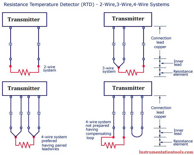
Difference Between 2 wire RTD, 3 wire RTD, and 4 wire RTD's
Les Paul Wiring Diagram - Humbucker Soup May 25, 2020 · Once you know the HOT and the GROUND wires for each pickup, installation is straightforward. Wire your guitar to resemble the diagram in Example 2. Example 2. The only thing that might seem strange about this diagram is that most people will not use the black wire from the third lug of the Volume to the back of the Volume pot.
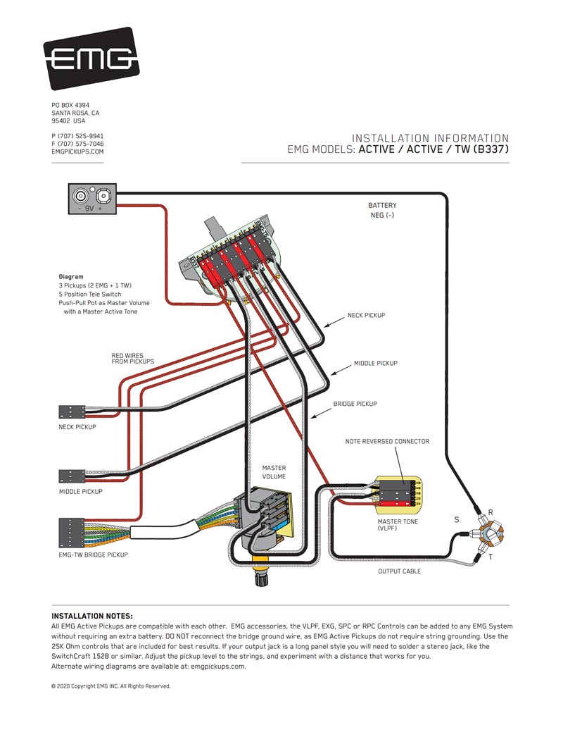
EMG Pickups / Top EMG Wiring Diagrams / Electric Guitar ...
3 Pickup Guitar Wiring Diagrams - GuitarElectronics.com Neck Coil Tap+Bridge Coil Tap 4. Neck Coil Tap+Middle 5. Neck Humbucker; 3 Single Coils. 3 Single Coils/5-Way Lever Switch/1 Volume/2 Tones-Typical Fender Stratocaster Wiring; 3 Single Coils/5-Way Lever Switch/1 Volume/2 Tones-1 Push-Pull for Neck+Bridge Option (7-Sound Strat) 3 Single Coils/5-Way Lever Switch/1(2) Volumes/2(1) Tone-1 Push-Pull ...

WOLFIGO New 1 PC or 6 PCS 3 Pin Way Ignition Coil Pack Wiring ...
Mercruiser Ignition Coil Wiring Diagram - Today Wiring ... Mercruiser Ignition Coil Wiring Diagram - Today Wiring Diagram - Mercruiser 4.3 Wiring Diagram Uploaded by Anna R. Higginbotham on Monday, February 11th, 2019 in category Wiring Diagram. See also Wiring Harness(Engine) - 1998 Mercruiser 4.3L [Alpha Efi] 4231017L1 - Mercruiser 4.3 Wiring Diagram from Wiring Diagram Topic.
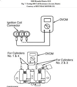
2000 Hyundai Elantra Loose Spark to Plugs: After the Motor Is ...
Coil-on-plug primary voltage and current (3-wire) Coil-on-plug primary voltage and current (3-wire) The purpose of this test is to examine the primary voltage and current within a 3 wire coil on plug unit. WARNING. This test involves measuring a potentially hazardous voltage. Please ensure you follow manufacturers' safety instructions and working practices and ensure the rated voltage for all ...

Seymour Duncan Telecaster Wiring Diagram | Seymour Duncan

Ignition Coil Pack(s)

not sure how to wire coils/dizzy......can you help? - AusRotary
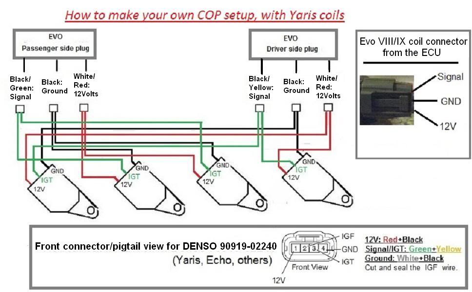
COP setup wiring (Denso 90919-02240, Yaris/Echo Schematics ...
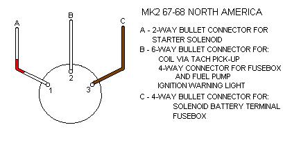
Ignition Switch Connections
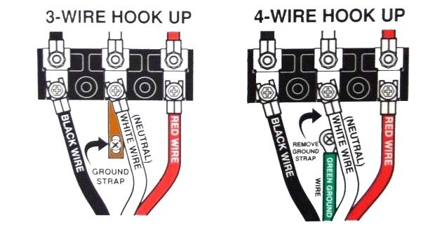
3-Wire Cords on Modern 4-Wire Appliances – JADE Learning
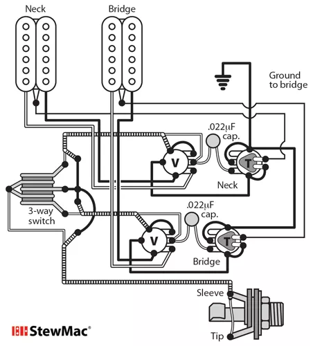
Switchcraft 3-way Toggle Switch - StewMac

How to wiring DC solenoid valve with 3 wire - General ...

VW Golf 3 1.6 ABU ignition coil check
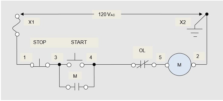
Understanding Three-Wire Control - Technical Articles

How to Wire an Illuminated Rocker Switch

Ignition Coil Pack(s)

Guitar Wiring Diagram 2 Humbuckers/3-Way Lever Switch/1 ...
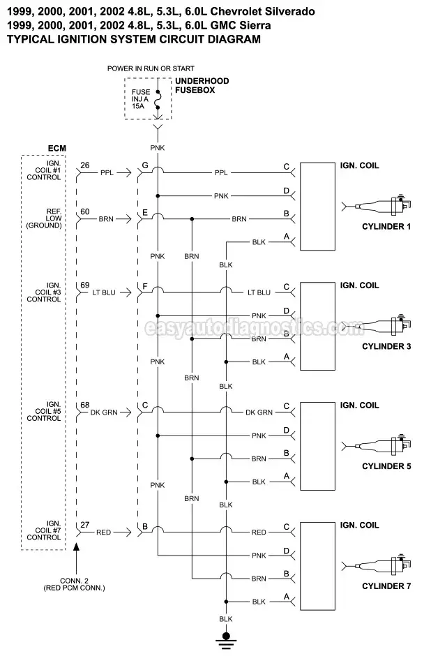
Ignition Coil Circuit Wiring Diagram (1999-2002 V8 Chevrolet ...

Buy Zinger 3 Wire Dump Trailer Remote Control Switch 12V for ...

How-to-wire-3-phase-electric

Three Phase Electrical Wiring Installation in Home - NEC & IEC
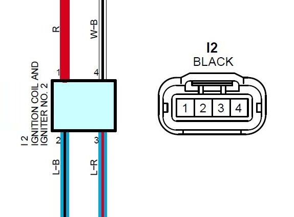
Cylinder 2 ignition coil wiring diagram 2002 ls430 ...

Golden Age Humbucker - StewMac
IronGear Pickups - Wiring

Electronics troubleshooting - Corsa Performance Marine
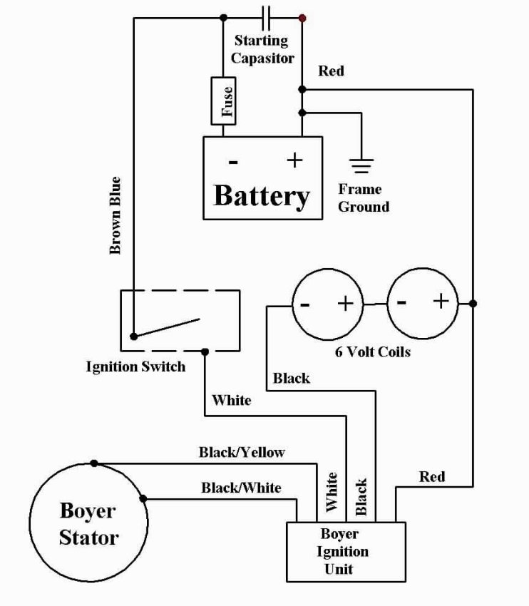
Old Britts Installing the Boyer Bransden MKIII Ignition Units ...
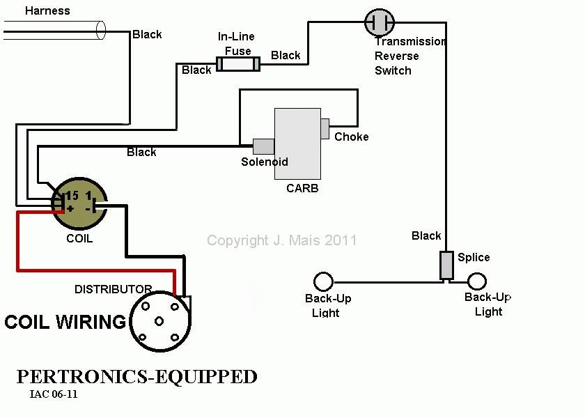
Coil Wiring Hook-Up's - Itinerant Air-Cooled

How to wiring DC solenoid valve with 3 wire - General ...

How to wire 3-phase
Jeep Liberty Questions - firing order and coil pack ...
0 Response to "44 3 wire coil diagram"
Post a Comment