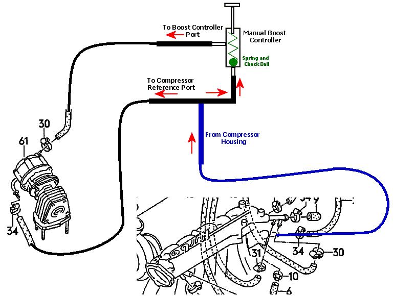
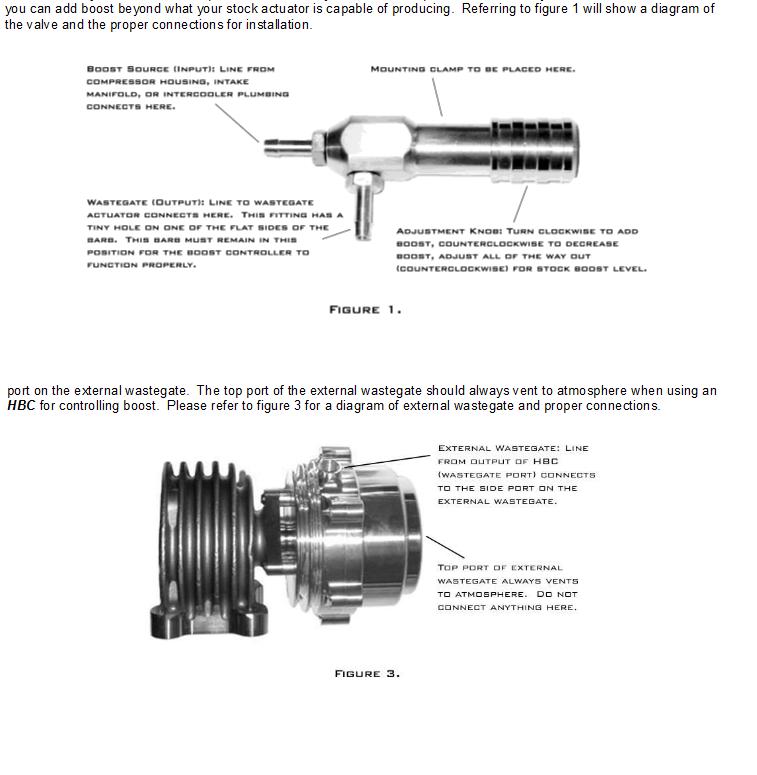
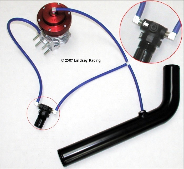
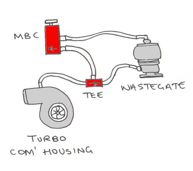
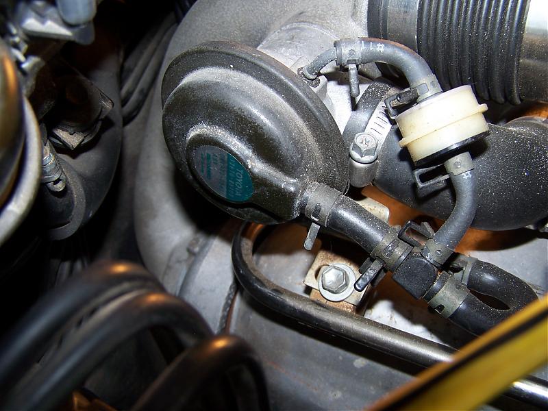
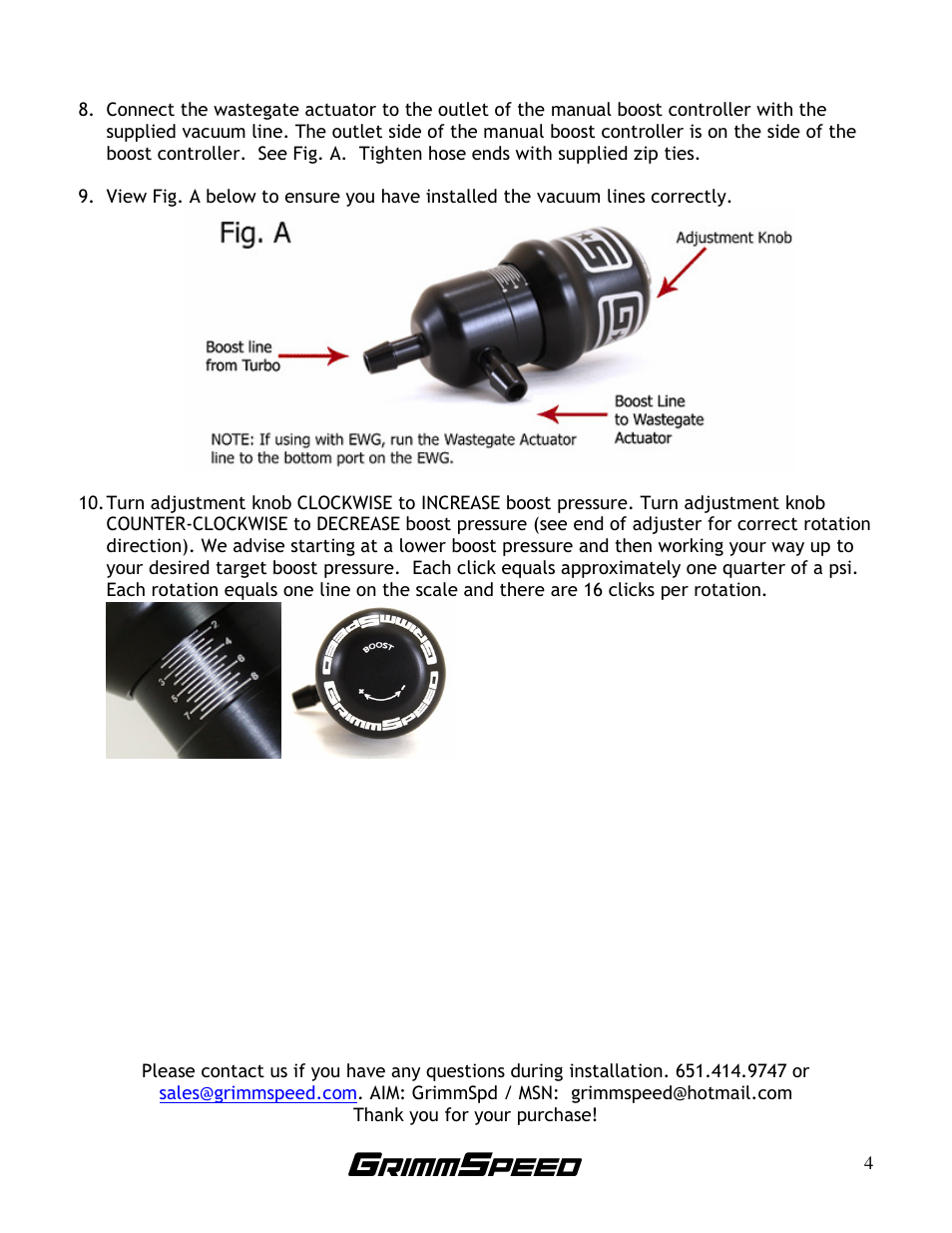
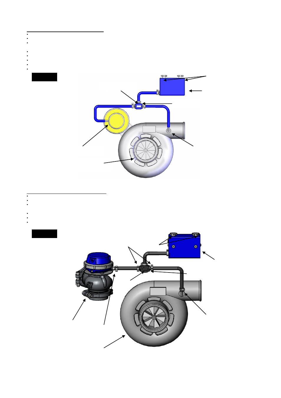
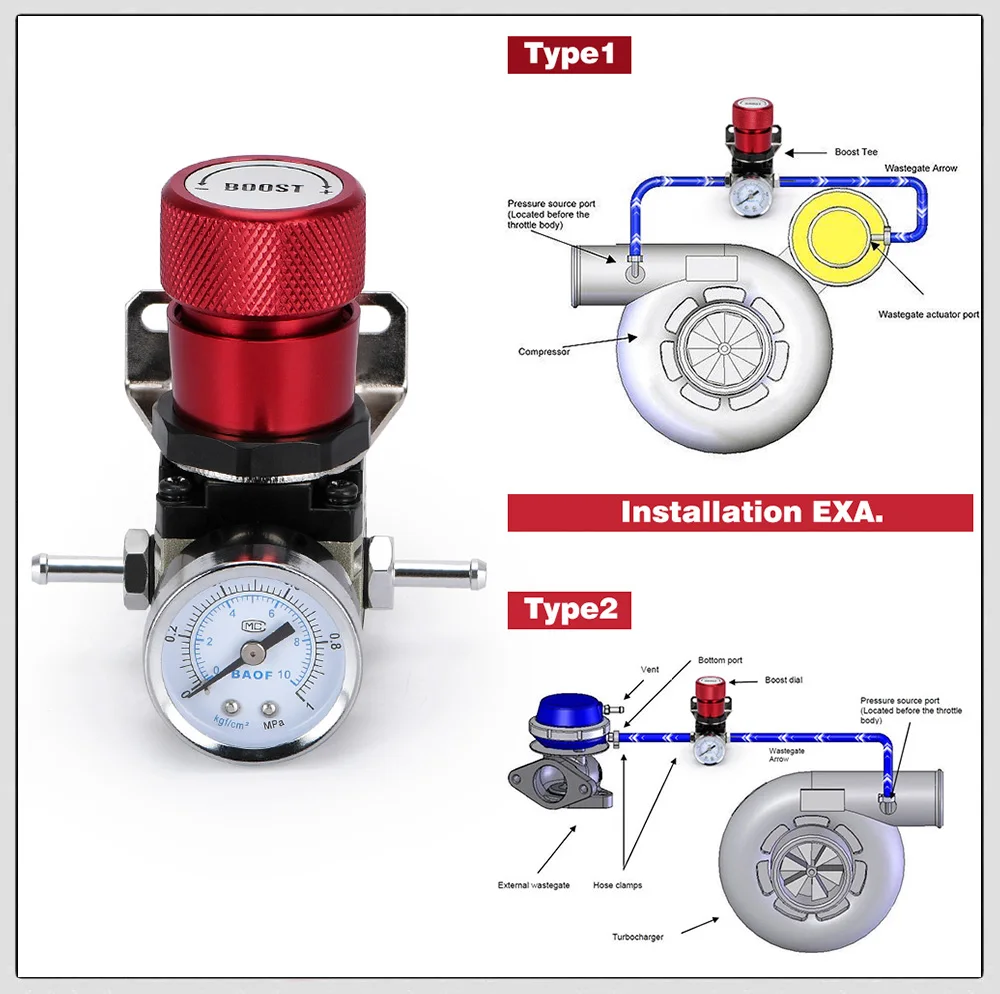
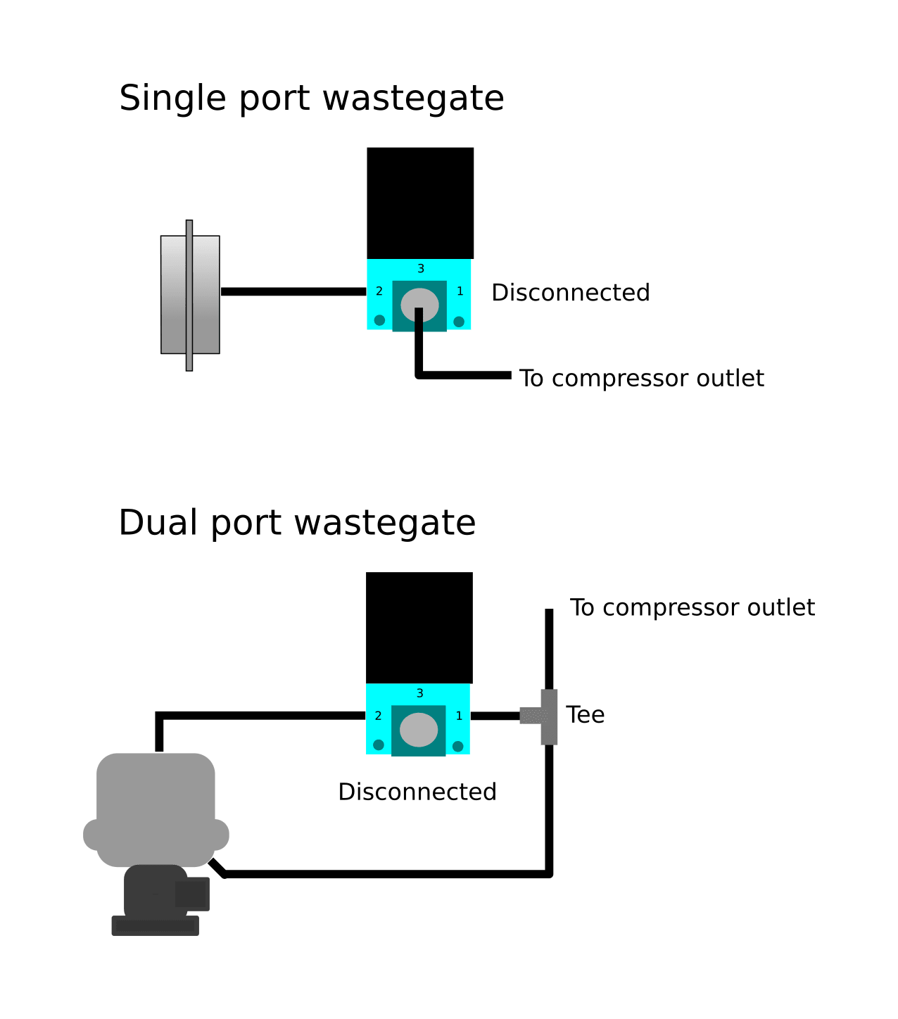
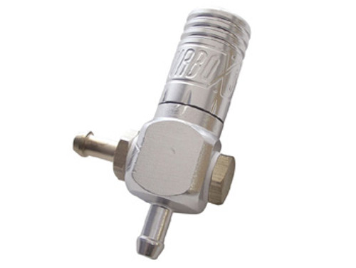
42 manual boost controller diagram
Illustrated Parts Lists and Installation/Owners Manuals - VMAC Illustrated Parts Lists and Installation/Owners Manuals. Last Modified on 10/11/2021 11:01 am PST. (These links will open in a new window) Installation/Owners Manuals. Illustrated Parts Lists (IPL's) Installer Reference Manual - This is the manual you receive when you complete the UNDERHOOD Installer Training. Owner's Manual - UNDERHOOD ... 7.3L Wiring Schematic Printable, very handy. | Page 2 ... 7.3L Wiring Schematic Printable, very handy. Handy Wiring Diagram that shows a Paper Trail of how the Electrical System Works for the 7.3L Powerstroke Engines, all Trucks, Excursions, Vans. It was a Copy I had to PhotoShop to make it Readable & Printable. it's very detailed and shows how every wire for each component routes to the PCM.
Ford Technical Documents - Optionally for a degree of manual control, you can insert an on/off switch in the antenna +12v line, you can then leave the mast at any height you desire â€" rather than the antenna raising and lowering with the switching on and off of the stereo. This works by interrupting power to the antenna while it is raising or lowering.
Manual boost controller diagram
2011 Ford F150 Fuse Diagram — Ricks Free Auto Repair ... 2011 Ford F150 Fuse Diagram for Battery Junction Box F11 30 Power Running Board (PBS) module F12 40 *50 Cooing fan low speed relay F13 30 Starter relay F14 30 Seat control switch, passenger side front F15 40 *50 Cooing fan high speed relay F16 - Not used F17 30 Trailer Brake Control (TBC) module. Telematics module F18 30 Upfitter relay 1 GReddy Electronics - No Limit Motorsport The GReddy PRofec B-spec. is one of the simplest, easy to use electronic boost controllers on the market today. Available in either Black or Clear Blue cases, the PRofec B-spec uses a reliable twin-solenoid valve control motor. There are two presets labeled Lo. and Hi., as well as a Balance knob to alter the wastegate boost response. What's the deal with inputs and outputs? - Havoc Speed Example: A nitrous or boost control solenoid may be opened and closed rapidly (60-80+ times per second) using pulse width modulation to control wastegates, or nitrous output. • Multi input - Can be configured as a 0-5V sensor input, 0-20v sensor input, thermistor temperature input, or high or low voltage input
Manual boost controller diagram. NBA 2K22 Controls Guide (PS5, Xbox Series X/S, PS4, Xbox ... September 10, 2021 Here are the full NBA 2K22 controls for PlayStation 4, PlayStation 5, Xbox Series X/S, and Xbox One. 1. NBA 2K22 On-Ball Offense Controls 2. NBA 2K22 Off-Ball Offense Controls 3. NBA 2K22 On-Ball Defense Controls 4. NBA 2K22 Off-Ball Defense Controls 5. NBA 2K22 Shooting & Finishing Controls 6. NBA 2K22 Passing Controls 7. Manual - PHP PHP Manual. Preface. Getting Started. Introduction. A simple tutorial. Installation and Configuration. General Installation Considerations. Installation on Unix systems. Installation on macOS. Free wiring diagrams! | Page 32 | Diesel Place Welcome to DieselPlace. Try gmupfitter.com as mentioned above in post #628. 1996 K3500 6.5L, ( "F" Eng #141 cast block) NV4500, crewcab, dually,Diamond Eye 4" Turbo Back Exhaust w/2.5" Flo-Pro Crossover, AirDog II DF165 w/ tank sock,delete,TD-Max boost controller,OPS extension hose,Glow Plug Harness,Glowshift Maxtow gauges,Boost & Fuel Pressure ... Geekvape User Manual Instruction Read Online/Download GeekVape H45 (Aegis Hero 2) Kit-User Manual. December 21, 2021 0. Post Views: 1,748 INSTRUCTIONS 1. Turn on/Turn off: Press the Fire button 5 times in quick succession within 2s to turn on the device.
Hks Evc Diagram - hks new electrice valve boost controller ... Hks Evc Diagram - 17 images - hks evc ez, full nonsequential diagram mazda rx7 forum, hks evc iii boost controller installation manual, hks evc vi manual pdf, MSD Performance Forums - Holley MSD 6530 Laptop Or Tablet... MR. GASKET. Holley has been the undisputed leader in fuel systems for over 100 years. Holley carburetors have powered every NASCAR® Sprint® Cup team and nearly every NHRA® Pro-Stock champion for four decades. Now, Holley EFI is dominating the performance world as well as our products for GM's LS engine. 6 Symptoms Of A Boost Leak (& How To Find It Easy ) A boost leak is a type of air leak in the intake path just before the engine cylinders. It is basically a loose clamp or damaged hose that cannot handle the turbo boost's pressure. Ignoring a boost leak will eventually reduce your turbo's life and in turn the car engine's life. Volvo Forum - MatthewsVolvoSite Chips, exhaust, larger turbos, bigger/slotted/drilled rotors, high performance brake pads, manual boost controllers, performance shocks/struts/springs, airbox mods and more! Also discussion on HID and Xenon lights, aftermarket foglights and other exterior lighting. 909 Topics 5225 Posts Last post Re: Build your own TCV ...
12V-24V PWM Motor controller circuit using TL494-IRF1405 12V DC motor speed control PWM circuit using TL494. This is a 12V DC motor speed control PWM circuit. Which using a TL494 (Switchmode Pulse Width Modulation Control IC) is a base for control DC Motor with pulse. Please detail more: - For Control speed motor 12V 150Wmax 15A. - R6 adjust speed motor. - Driver Motor by Mosfet IRFZ48.x 2pcs. msi Z590 PRO Wi-Fi/ Z590-A PRO Motherboard User Guide ... Please refer to the TPM security platform manual for more details and usages. JCI1: Chassis Intrusion Connector This connector allows you to connect the chassis intrusion switch cable. Using chassis intrusion detector Connect the JCI1 connector to the chassis intrusion switch/ sensor on the chassis. Close the chassis cover. Eagle Autorouter Width - Wiring Schematic Diagram Eagle defaults to a 13.77 mil via, which equates to a 0.35mm hole diameter. Open your pcb layout (.brd) file from your autodesk eagle control panel. Click change (the little wrench icon on the left toolbar), select the width, then click the trace you want to change. You will also notice that the trace width, drill size, and clearance values for ... The Definitive Guide To The VW Mk7 GTI EA888 Engine (Gen 3) The Mk7 GTI is equipped with an evolution of the 2.0t turbocharged Volkswagen 'TSI' EA888 generation of engines. Although they share the same fundamental look, a limited number of parts, and utilize similar concepts, the EA888 Gen 3 of the Mk7 GTI features many distinct differences from the Gen 1 and Gen 2 variants.
TIMEGUARD 7 Day Digital Instruction Manual - Manuals+ Connection Diagram). • Secure the terminal cover back into place using the fixing screw. 5. Connection Diagram The terminals are marked as follows on the bottom of the wall plate; Note: this device needs to be left to charge for a minimum of 15 minutes once powered up, before it will operate. 6. Battery
Understanding SG3525 IC Pinouts - Homemade Circuit Projects Pin#4 (Osc. Out): It's the oscillator output of the IC, the frequency of the IC may be confirmed at this pin out. Pin#5 and #6 (Ct, Rt): These are termed CT, RT respectively.Basically these pinouts are connected with an external resistor and a capacitor for setting up the frequency of the inbuilt oscillator stage or circuit.
What is cascade control? | Instrumentation and Control ... The operator would be able to change the modes, there are three modes and they are manual mode, auto mode, and cascade mode. In manual mode, the set point of the flow controller tracks the actual flow. In the auto mode, the output of the temperature controller tracks the set point of the flow controller.
NCE Owners Manual: SB5 Smart Booster - DCCconcepts NCE Owners Manual: SB5 Smart Booster. If you have any questions or feedback regarding this advice, please feel free to contact us at salesuk@dccconcepts.com or via the enquiries form on our Contact Us page. Fullscreen Mode.
Simarine Pico Battery Monitor: Installation ... - FarOutRide Buy on Amazon. 1- With the help of the gasket, locate where to install the sensor. mark the center for drilling and mark the outside diameter (to help position the sensor later): 2- Drill using a 1-3/8" hole-saw: 3- Find the correct alignement of the gasket on the screw holes, then apply a bead of Silicone II around.
Wiring and Sensors If you are using a V3 main board, use this wiring diagram .) External Wiring with a V3.0 Main Board Because of the added stepper IAC, ignition control, and PWM idle capabilities of the MegaSquirt-II, the V3.0 main board has been designed with these functions in mind. As a result, five additional connections are made at the DB37 connector.
Subaru Flex Fuel Tuning Guide - Customer Support Center ... See applicable FSM for detailed wiring diagrams. DTC functionality for Ethanol Sensor Low and High voltage errors is provided via "C0BB1" and "C0BB2" custom DTC codes. When the C0BB1 or C0BB2 DTC is present, ethanol content will be locked to the last known good value and the boost control system will be disabled (WGDC capped to 0.0%).
My350z - Largest online forum for the Nissan 350Z and 370Z. Hey all, I've been having an issue with my 2004 350z. Basically the stock fans won't turn on, whether it's driving, A/C is on, or in the built in self test mode. I've verified that both fans work by…. By LNVFX - April 24, 2022.
Adafruit Huzzah Wiring - how to connect ati pm dimbar to ... Adafruit Huzzah Wiring - 16 images - wiring diagram for honeywell thermostats new honeywell, pinouts adafruit feather huzzah esp8266 adafruit, adafruit huzzah esp8266 breakout id 2471, wiring diagram and flowchart wiring diagram keyless,
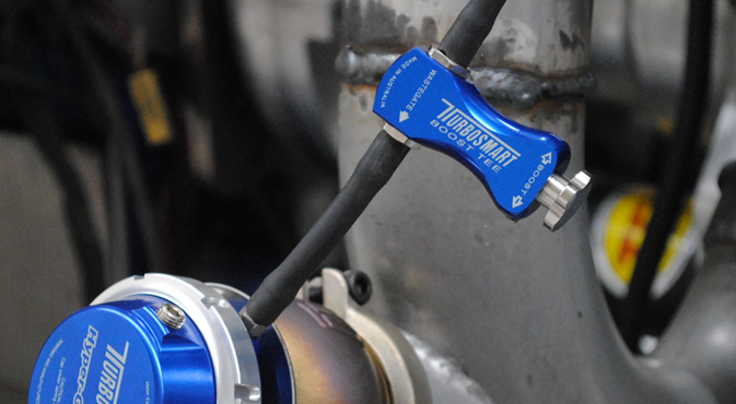
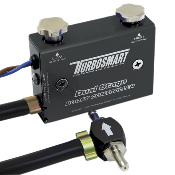
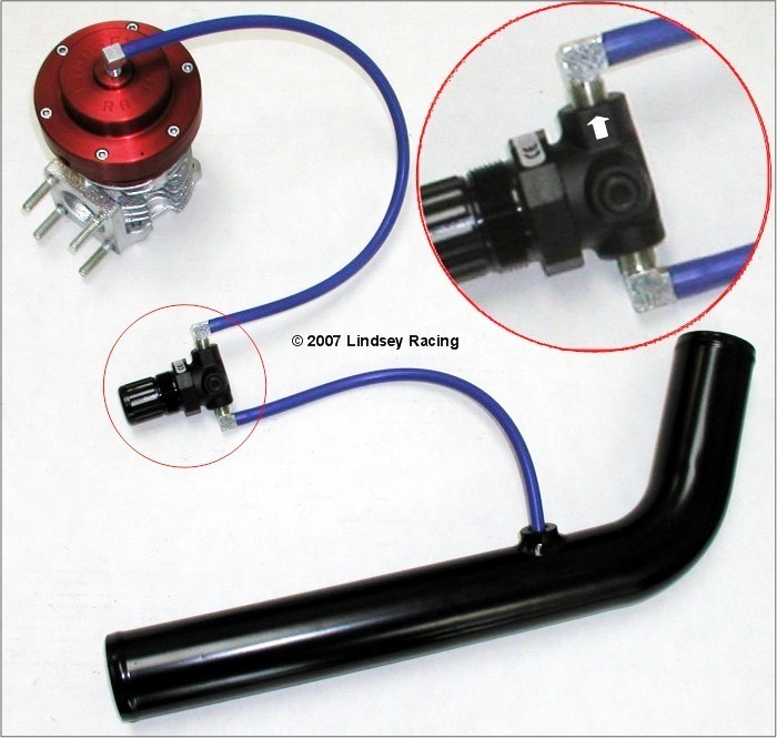
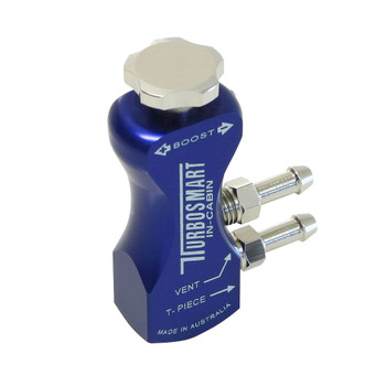
How Does a Boost Controller Work? • Turbosmart ... There Are Two Type of Boost Controllers Offering up to two boost settings, the mechanical (gated) boost controllers can easily be set and adjusted by the driver and controlled via a switch. They are easy to fit, simple in operation and require little maintenance. 1. Mechanical (Gated) Boost Controllers
S550 Mustang Fuse Panel Diagrams | 2015-21 - LMR.com FOLLOW: 2015 mustang , s550 mustang. All too often we at Late Model Restoration have noticed how hard it is to find a thorough S550 Mustang fuse panel diagram guide so we wanted to make this a little easier for enthusiasts like yourself. Check them out below and solve your pesky fuse issues for your 2015-21 year model Mustang today!
What's the deal with inputs and outputs? - Havoc Speed Example: A nitrous or boost control solenoid may be opened and closed rapidly (60-80+ times per second) using pulse width modulation to control wastegates, or nitrous output. • Multi input - Can be configured as a 0-5V sensor input, 0-20v sensor input, thermistor temperature input, or high or low voltage input
GReddy Electronics - No Limit Motorsport The GReddy PRofec B-spec. is one of the simplest, easy to use electronic boost controllers on the market today. Available in either Black or Clear Blue cases, the PRofec B-spec uses a reliable twin-solenoid valve control motor. There are two presets labeled Lo. and Hi., as well as a Balance knob to alter the wastegate boost response.
2011 Ford F150 Fuse Diagram — Ricks Free Auto Repair ... 2011 Ford F150 Fuse Diagram for Battery Junction Box F11 30 Power Running Board (PBS) module F12 40 *50 Cooing fan low speed relay F13 30 Starter relay F14 30 Seat control switch, passenger side front F15 40 *50 Cooing fan high speed relay F16 - Not used F17 30 Trailer Brake Control (TBC) module. Telematics module F18 30 Upfitter relay 1











0 Response to "42 manual boost controller diagram"
Post a Comment