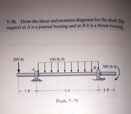
41 draw the shear diagram for the shaft.
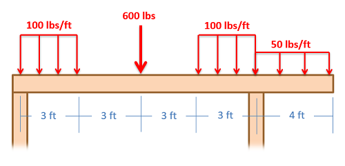
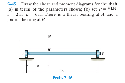
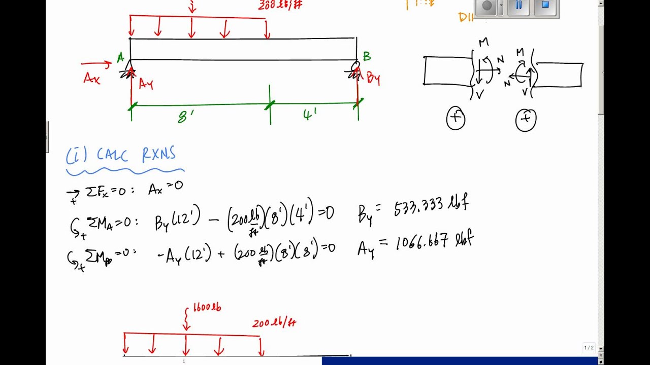
Draw the shear and moment diagrams for the double overhanging beam. So sum of moments at any point or forces in any direction are 0 3. 3 ft 3 ft 200 lbft 400 lb 6 ft 400 lb a b. Assume the supports at a is fix c is roller and b is pin connections. The shaft is supported by a smooth thrust bearing at a and a... The bearings at and exert only vertical reactions on the shaft. A hollow rectangular steel beam is 18 cm deep by 10 cm wide, outside dimensions. The walls are 2 cm in thickness. From the shear and moment diagram, the maximum vertical shear.
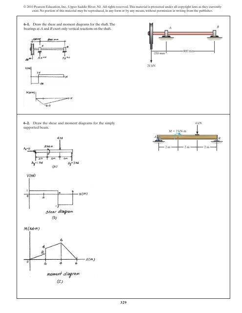
329 6 1 draw the shear and moment diagrams for shaft. Show transcribed image text part a draw the shear diagram for the beam.
Draw the shear diagram for the shaft.
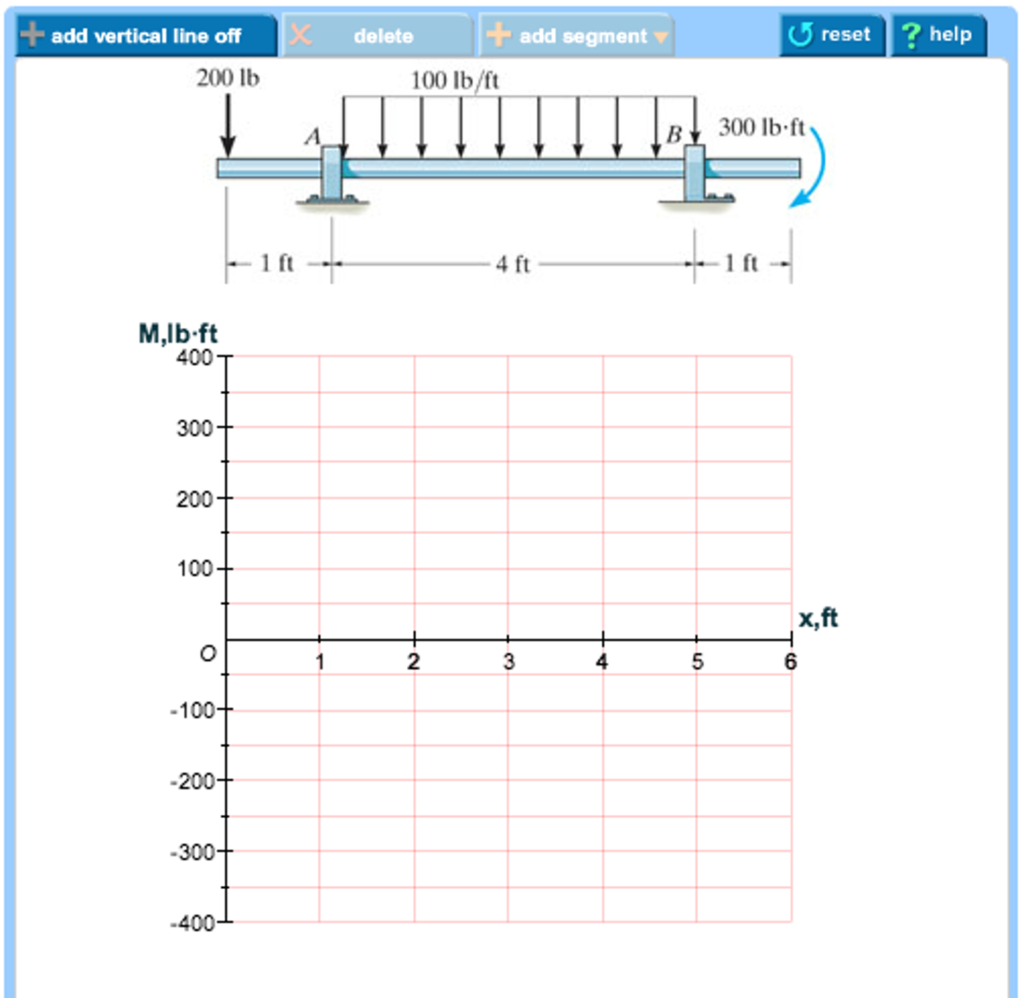
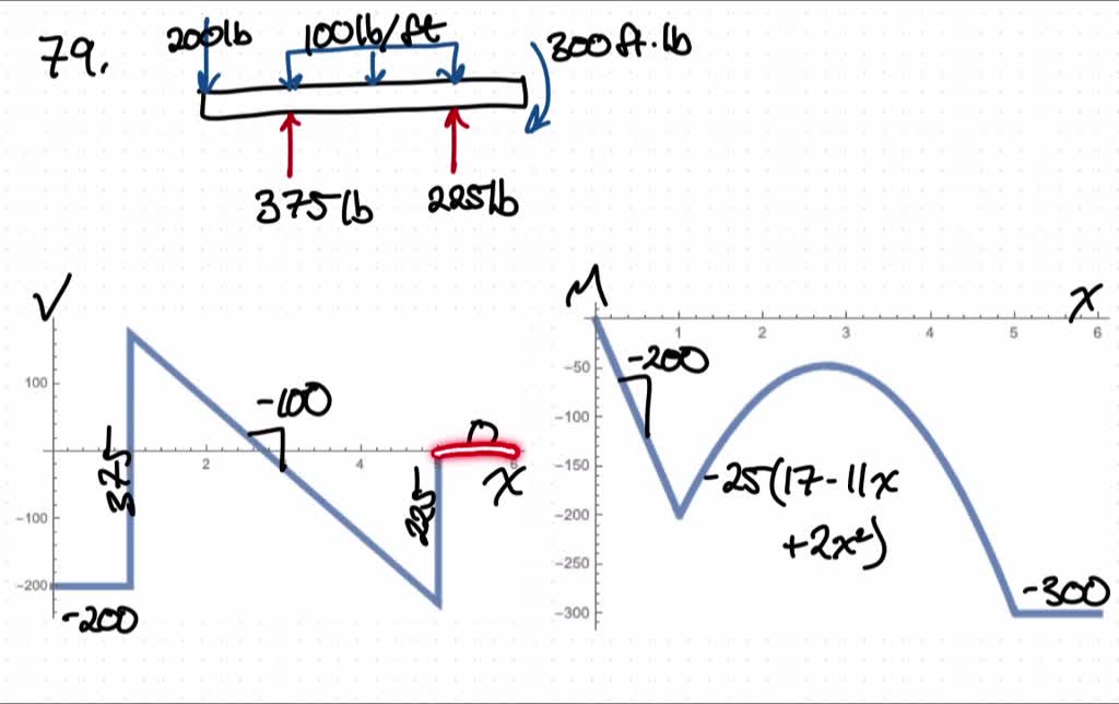
Potassium carbonate solution reacts with aqueous hydrobromic acid to give a solution of potassium bromide, carbon dioxide gas, and water. Write the molecular equation and the net ionic equation for the reaction. ‰ The shear force and bending moment diagrams are convenient visual references to the internal forces in a beam; in particular, they identify the maximum values of V and M. ƒ Draw a FBD for the part of the beam lying either to the left or to the right of the cutting plane, whichever is more convenient. To draw the shear force diagram we take the distances on x-axis and the shear force values on y-axis and join the points. Wherever there is point load the shear force diagram will be parallel to...
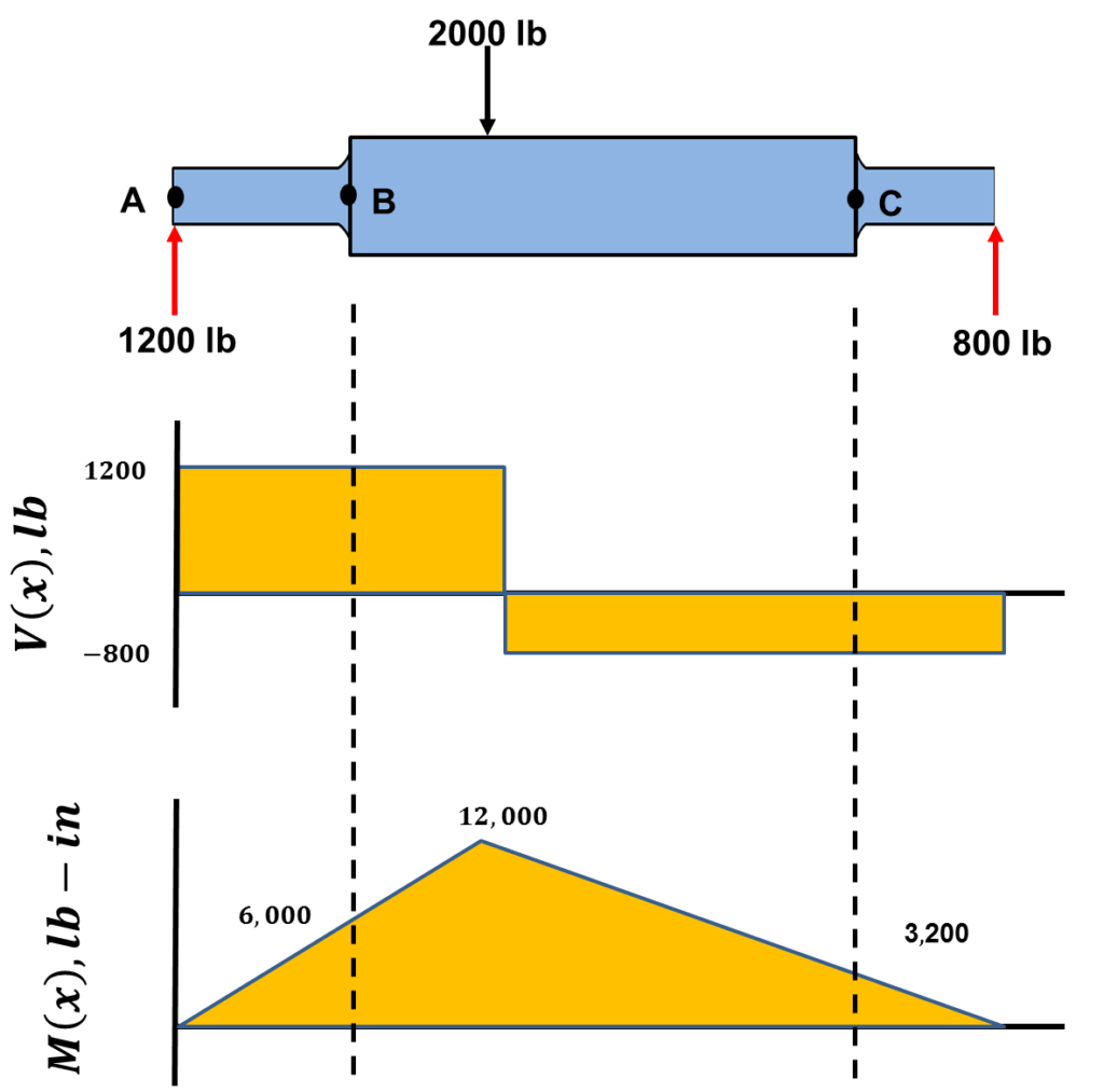
Draw the shear diagram for the shaft.. Draw the shear and moment diagram for the beam shown in figure. The resulting graphics are called the shear diagram and moment diagram. Since the same x was used for all three sections, the each equation for each section can be easily plotted as shown at the left. Draw the shear and moment diagrams for shaft bearings at a b exert only vertical reactions on problem diagrams for the cantilever beam shown in figure draw shear force and. The next force is 10 lb. A shearing force occurs when a perpendicular force is applied to static material in this case a beam. Shaft Calculator. Bending Moment Diagram is powered by the team at SkyCiv Engineering - who offer Student and Professional packages that give users access to a variety of Structural Engineering The calculations are only set to draw the shear force and bending moment of a beam at the moment. To complete a shear force and bending moment diagram neatly you will need the following materials. - Knowing how different forces effect beams is important to be able to calculate the shear and bending moments. - A point force will cause a rectangular shear and a triangular bending moment.
Shear and bending moment diagrams are analytical tools used in conjunction with structural analysis to help perform structural design by determining the value of shear force and bending moment at a given point of a structural element such as a beam. Expert answer expert answer draw the shear and moment diagrams for loaded end beam where couple mi consider a cantilever beam subjected to uniform distributed load as indicated below l. Draw the shear and moment 329 6 1 Draw The Shear And Moment Diagrams For The Shaft The. The bearings at A and B exert only vertical reactions on the shaft. © 2010 Pearson Education, Inc., Upper Saddle River, NJ. 6-3. The engine crane is used to support the engine, which has a weight of 1200 lb. Draw the shear and moment diagrams of the boom ABC when it is in the horizontal position... No portion of this material may be reproduced, in any form or by any means, without permission in writing from the publisher. 6-2. Draw the shear and moment diagrams for The bearings at A and D exert only vertical reaction on the shaft. The loading is applied to the pulleys at B and C and E. 14 in.
Also draw shear and moment diagrams specifying values at all change of loading positions and at 778 draw the shear and moment diagram for the beam. Name id date mte 119 statics homework 7 7 78 as a picture shown. Draw the shear and moment diagrams for the shaft. I attached the prob. Begin the shear diagram by drawing a horizontal line, this is the line for zero shear. I like to draw my shear diagrams directly below the actual member so that they line up and I designate my shear diagrams with a big V. The beam is 20ft long divided into 5 foot sections. Bending Moment Diagrams. Shear Force Diagrams. Calculate the Deflection of Steel, Wood and Other Materials. Use this beam span calculator to determine the reactions at the supports, draw the shear and moment diagram for the beam and calculate the deflection of a steel or wood beam. Draw the shear and moment diagrams for the shaft.The bearings at A and B exert only vertical reactions on the shaft. © 2010 Pearson Education, Inc., Upper Saddle River, NJ. All rights reserved.This material is protected under all copyright laws as they currently exist.
But to draw a shear force and bending moment diagram, we need to know how these values change across the structure. What we really want is an We want to determine the shear force and bending moment diagrams for the following simply supported beam. You can continue reading through the...

Shear and moment diagrams draw the shear and moment diagrams for the following beam 12 ft. B 875x 0 v 5875 150x6 lb c f y 0. M 450x 4 0 v 1050 150x cf y 0 Determine The Equation Of The Slope And Elastic Curve Ei Is Constant. 329 6 1 Draw The Shear And Moment Diagrams For The Shaft The.

- The Free-body diagram of the portion BC of the shaft must include the elementary shearing forces dF perpendicular to the radius ρ of the shaft. • The expression for the angle of twist of the previous equation may be used only if the shaft is homogeneous (constant G) and has a uniform cross...
Draw the shear diagram for the beam. Consider the left or the right portion of the section. Imagine the beam is the carrot and a point load is the knife. 2 draw the moment diagram for the beam. A shearing force occurs when a perpendicular force is applied to static material in this case a beam.

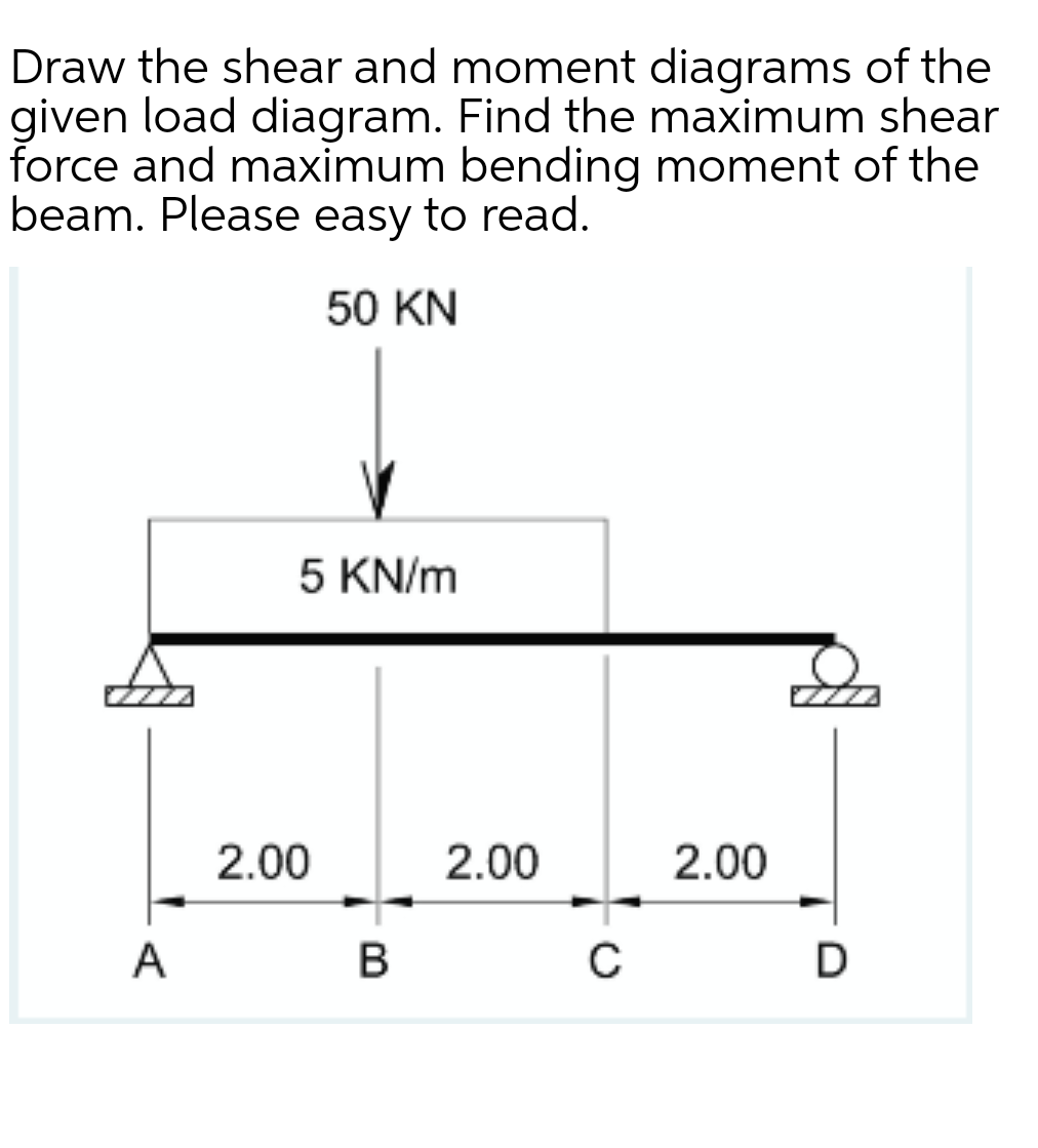
Draw the shear and bending-moment diagrams for the beam and loading shown, and determine the maximum absolute value (a) of the shear, (b) of the bending moment. SOLUTION Origin at A: Reaction at A: From A to C
The shaft is supported by a smooth thrust bearing at A and smooth journal bearing at D. If the shaft has the cross section shown, determine the *6-92. Determine the smallest allowable diameter of the shaft which is subjected to the concentrated forces. The journal bearings at A and B only support...
Transcribed Image Text from this Question. Draw the shear diagram for the shaft.
6-1. Draw the shear and moment diagrams for the shaft. Draw the shear and moment diagrams for the 6 kip 8 kip compound beam which is pin connected at B. A C B 4 ft 6 ft 4 ft 4 ft 331 06 Solutions 46060_Part1 5/27/10 3:51 PM Page 332 © 2010 Pearson Education, Inc., Upper Saddle River, NJ.
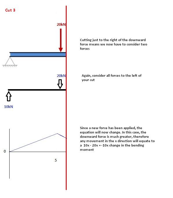
3 Shear and moment diagram Axial load diagram Torque diagram Both of these diagrams show the internal forces acting on the members. 13 Boundary cond for V and M M=5x M=10-5x. 14 Solve it Draw the shear and moment diagrams for simply supported beam.
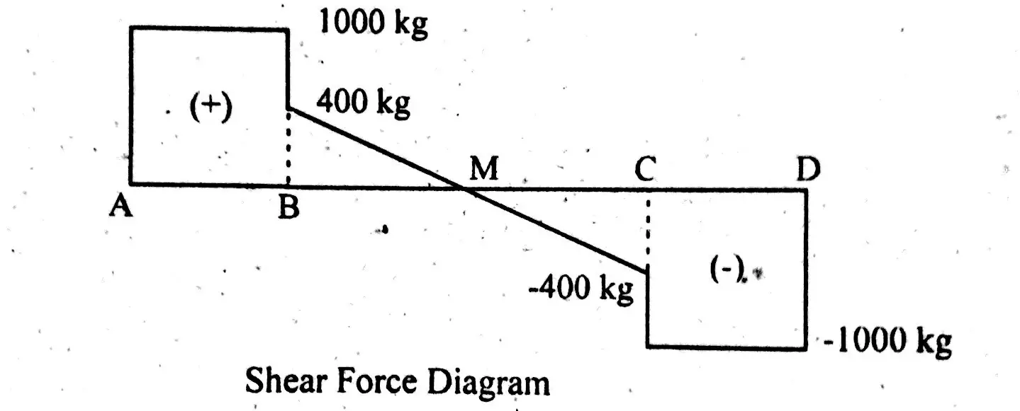
There are various methods of drawing shear force and bending moment diagram for a beam . The selection of suitable method depends on the degree of Now calculate the shear force at different points(sections) on the beam and while drawing the diagram clockwise shear force is taken as...

Draw the shear and moment diagrams for shaft bearings at a b exert only vertical reactions on problem diagrams for the cantilever beam shown in figure draw shear force and. Useful for second year mechanical engineering. Draw the shear diagram for the beam. The next force is 10 lb.

This is a tutorial to make shear force diagram and bending moment diagram easily for a simply supported beam loaded with concentrated loads. the method...
To draw the shear force diagram we take the distances on x-axis and the shear force values on y-axis and join the points. Wherever there is point load the shear force diagram will be parallel to...

‰ The shear force and bending moment diagrams are convenient visual references to the internal forces in a beam; in particular, they identify the maximum values of V and M. ƒ Draw a FBD for the part of the beam lying either to the left or to the right of the cutting plane, whichever is more convenient.
Potassium carbonate solution reacts with aqueous hydrobromic acid to give a solution of potassium bromide, carbon dioxide gas, and water. Write the molecular equation and the net ionic equation for the reaction.
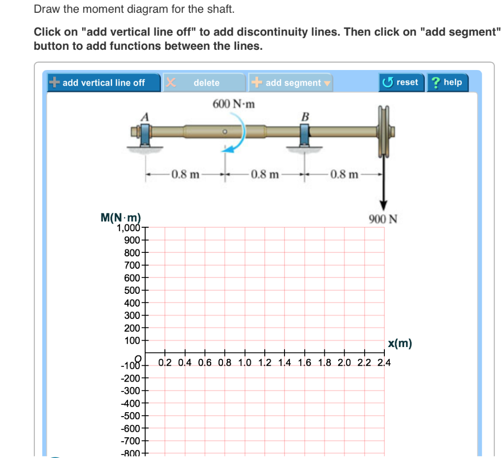


0 Response to "41 draw the shear diagram for the shaft."
Post a Comment