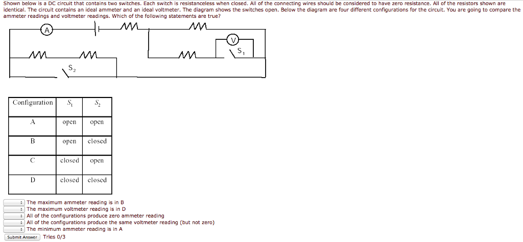
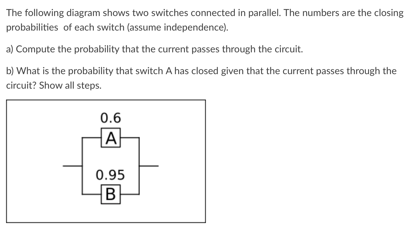
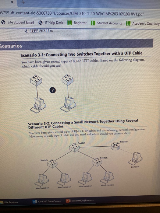
44 you have two switches connected together as shown in the following diagram
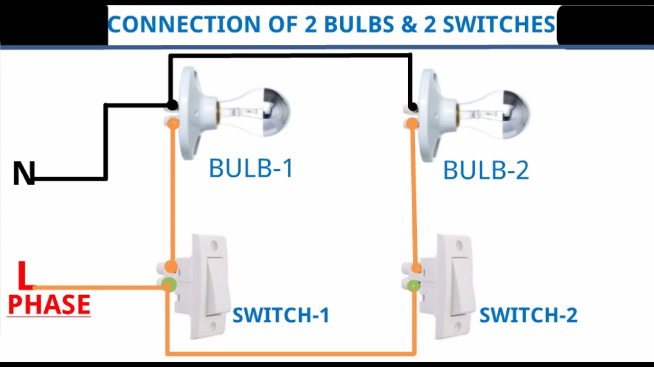
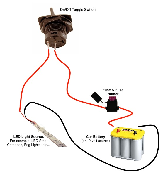
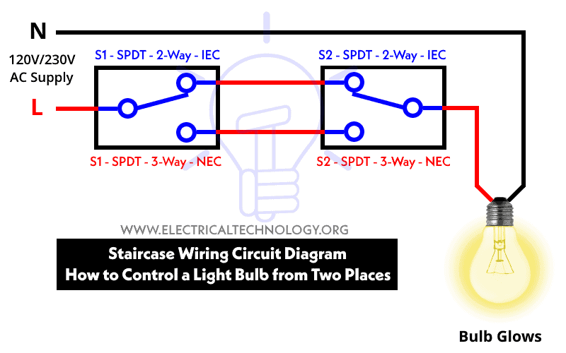
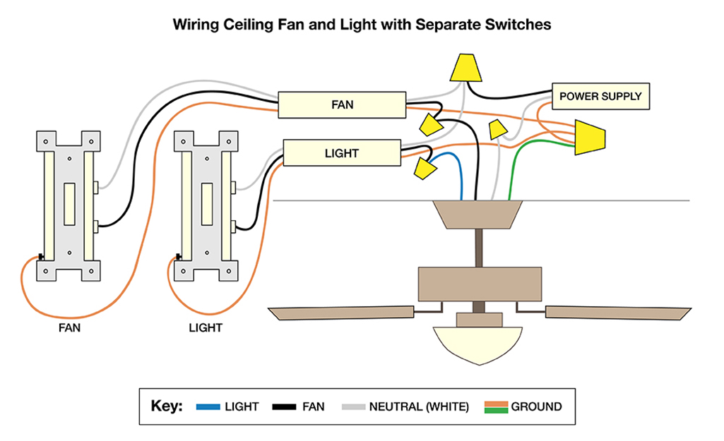
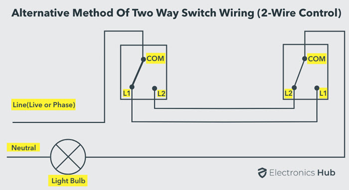
When you have the circuit working correctly, move on to question 2. If you need to, you can troubleshoot your circuit by looking at the following: If the lamp doesn't light up, but the wires get hot, you may have a short circuit. This means that the lamp is not connected correctly in the circuit, or that it is faulty. Procedure: Connect the two single way switches, light bulb in parallel to the power supply as shown in fig below. Keep in mind that one of the switches S1 or S2 must be closed to complete the circuit. If there are more switches connected in parallel with electrical appliance i.e. light point, one of them must be at ON position to operate the load.
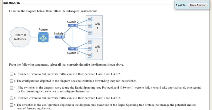
You have two switches connected together as shown in the following diagram. How many broadcast domains are in the network shown? ... Computers A and B are on the same VLAN and are separated by two switches as shown in the exhibit. Computer A sends a frame to Computer B. ... You manage a network with two switches. The switches are connected ...

You have two switches connected together as shown in the following diagram
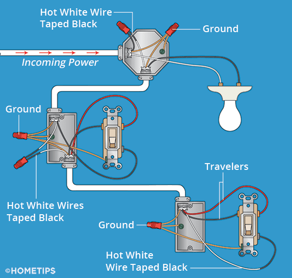
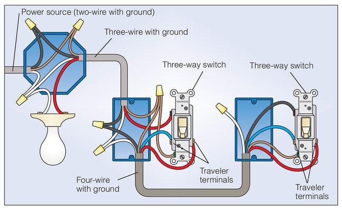
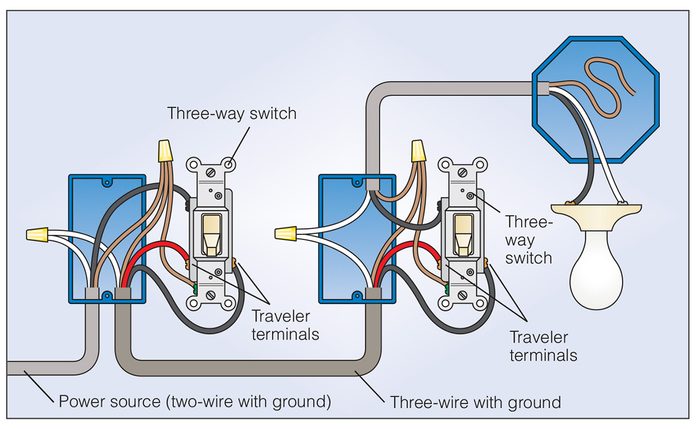
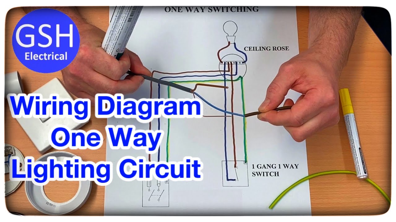
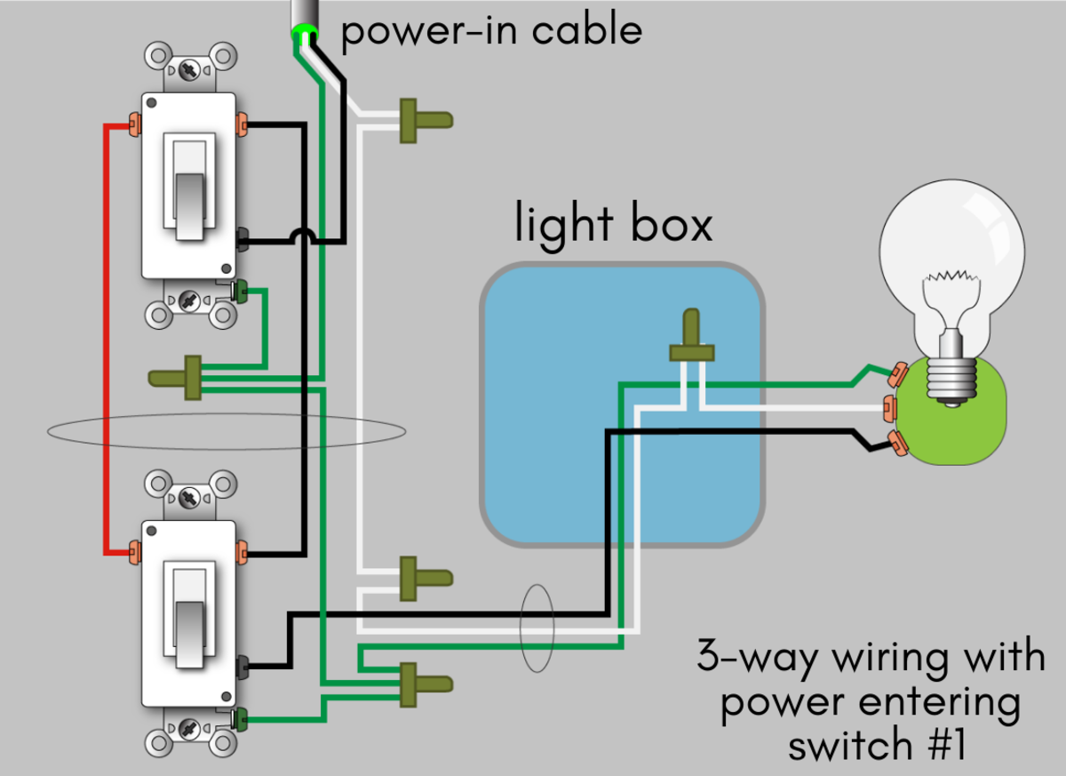
Basic arrangement of the 3-way switch. (Shown in the white box is a simple diagram that depicts the function of the three-way switch.) The main thing to remember when you wire two way switches is that they are the same as wiring in a single-pole switch, except you must have two additional wires attaching the two switches together as illustrated in the picture. You enter the show ip route command and receive the output as shown in the exhibit.Which of the following is true? (Select two.) VLAN 11 has a virtual p address in the 10.1.11.0 network. Traffic sent within vlans 2,3, and will be routed on the 3550 switch. You have configured inter-VLAN routing on a Catalyst 3550 switch. Examine this schematic diagram: Light bulb Switch Battery Now, without moving the following components, show how they may be connected together with wires to form the same circuit depicted in the schematic diagram above: + Battery - Light bulb Switch file 00069 Question 7
You have two switches connected together as shown in the following diagram. Configure the Switch Port to Carry Both Voice and Data TrafficWhen you connect an IP phone to a switch using a trunk link, it can cause high CPU utilization in the switches. As all the VLANs for a particular interface are trunked to the phone, it increases the number of STP instances the switch has to manage. You could make the circuit by laying out the cell and lamp on the table as shown in the circuit diagram, then joining them using wires If you have to draw a circuit diagram: draw the circuit ... Now, without moving the following components, show how they may be connected together with wires to form the same circuit depicted in the schematic diagram above: Reveal answer Follow-up question: suppose the circuit were built like this but the light bulb did not turn on when the switch was closed. In some situations we have two switches, each setup to route for its own broadcast domain, which we want to connect together. In this situation we no longer have a need to use Trunk or General mode between the switches. Instead we can create a common VLAN that will be used for the connection between the two switches.
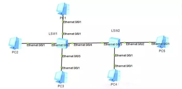
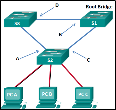
you have two switches connected together as shown in the following diagram. How many broadcast domains are there in the network? 2. Which of the following statements describe how VLANs effect broadcast traffic within an internetwork? Devices on the same VLAN have the same subnet address Broadcast traffic is transmitted only within a VLAN You have two switches connected together as shown in the following diagram. How many broadcast domains are there in the network shown? See Page 1. You have two switches connected together as shown in the following diagram. How many broadcast domains are there in the network shown? 2 Which of the following benefits apply only to creating VLANs with switches and not to segmenting the network with regular switches? You can create multiple broadcast domains. Draw a circuit diagram showing two electric lamps connected in parallel together with a cell and a switch that works both lamps. Mark an â'¶ on your diagram to show where an ammeter should be placed to measure the current.
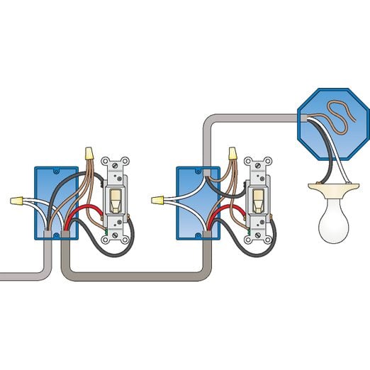
Now with that said, just look at the switch again and look at the circuit. There you have it, 3-way switch wiring simplified. Take notice of the ground wire. It's very important that the ground or bare copper wire is connected to the green screws on the switches. All grounds are connected, and the ground is connected at the light when possible. you have two switches connected together as shown in the following diagram. How many broadcast domains are there in the network? 2. Which of the following statements describe how VLANs effect broadcast traffic within an internetwork? Devices on the same VLAN have the same subnet address Broadcast traffic is transmitted only within a VLAN The first switch COM terminal connected to phase and second switch COM terminal is connected to one end of the bulb and the other end of the bulb is connected to neutral AC supply. The L 1 and L 2 terminals of both the switches are connected together. The two-wire control two-way switch is shown in the below figure. Two-Wire Control Two Way Switch Objects A and B are charged as shown in the diagram. A and B are brought together and touched. Which is the correct ... 40. The two ends of a wire are connected to a galvanometer, forming ... Which statement describes the diagram shown of a switch-controlled circuit? A. The switches are in series and this is an \AND" circuit.
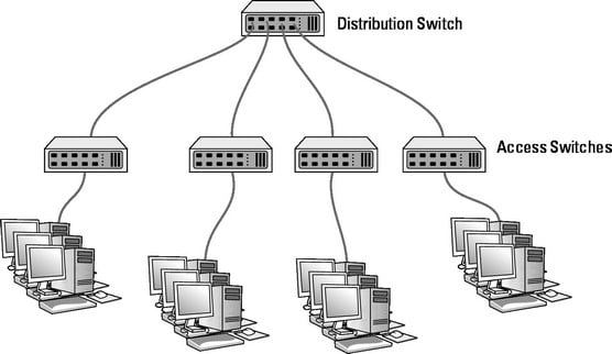
Each connection from a single PC to a Layer 2 switch is ONE Collision domain. For example, if 5 PCs are connected with separate cables to a switch, we have 5 Collision domains. If this switch is connected to another switch or a router, we have one collision domain more. If 5 Devices are connected to a Hub, this is ONE Collision Domain.
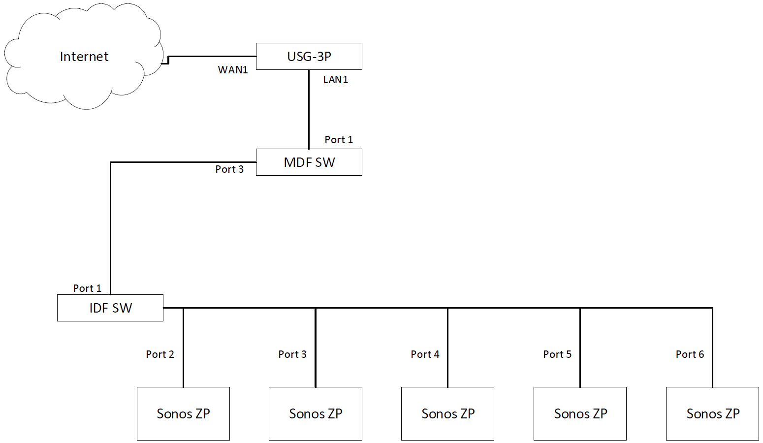
Marquitta, What you are looking to do is expand your network using two basic switches. All you need to do is connect the second switch to the first switch USING ONE SINGLE CABLE (having two connections between these switches would cause a loop, bringing disaster).). Any port on each switch will do.
Cascading switch is a traditional way to connect multiple Ethernet switches, which comes with various methods involving diverse network topologies. By cascading more than one switch together, users can have multiple ports interconnecting each of the switches, all of which can be configured and managed independently in the group.
A battery of emf 24 V and negligible intemal resistance is connected to a resistor network as shown in the circuit diagram in the diagram below. (a) Show that the resistance of the single equivalent resistor that could replace the four resistors between the points A and B is 50 Ω.
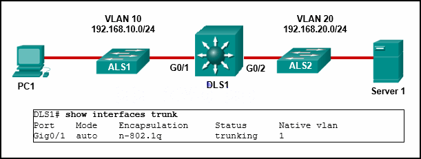
Cisco Catalyst switches CAT1 and CAT2 have a connection between them using ports FA0/13. An 802.1Q trunk is configured between the two switches. On CAT1, VLAN 10 is chosen as native, but on CAT2 the native VLAN is not specified. What will happen in this scenario? A. 802.1Q giant frames could saturate the link.
Ethernet switches link Ethernet devices together by relaying Ethernet frames between the devices connected to the switches. By moving Ethernet frames between the switch ports, a switch links the traffic carried by the individual network connections into a larger Ethernet network.. Ethernet switches perform their linking function by bridging Ethernet frames between Ethernet segments.
Section 4.5. Which of the following are reasons to configure VLANs on a switch as opposed to using switches without VLANs? (Select two.) Increased number of broadcast domains. Increased security. You have two switches connected together as shown in the following diagram.
Set up a parallel circuit with two cells in series with each other and three torch light bulbs in parallel with each other. Insert an ammeter in series between the cells and the first pathway as shown in the diagram. Measure the current strength using the ammeter. Remove the ammeter and close the circuit again.

Multiple Light Wiring Diagram. This diagram illustrates wiring for one switch to control 2 or more lights. The source is at SW1 and 2-wire cable runs from there to the fixtures. The hot and neutral terminals on each fixture are spliced with a pigtail to the circuit wires which then continue on to the next light.
Which of the following benefits apply only to creating VLANs with switches and not to segmenting the network with regular switches? You can create multiple broadcast domains you have two switches connected together as shown in the following diagram.

Examine this schematic diagram: Light bulb Switch Battery Now, without moving the following components, show how they may be connected together with wires to form the same circuit depicted in the schematic diagram above: + Battery - Light bulb Switch file 00069 Question 7
You enter the show ip route command and receive the output as shown in the exhibit.Which of the following is true? (Select two.) VLAN 11 has a virtual p address in the 10.1.11.0 network. Traffic sent within vlans 2,3, and will be routed on the 3550 switch. You have configured inter-VLAN routing on a Catalyst 3550 switch.
Basic arrangement of the 3-way switch. (Shown in the white box is a simple diagram that depicts the function of the three-way switch.) The main thing to remember when you wire two way switches is that they are the same as wiring in a single-pole switch, except you must have two additional wires attaching the two switches together as illustrated in the picture.


0 Response to "44 you have two switches connected together as shown in the following diagram"
Post a Comment