40 what is context diagram
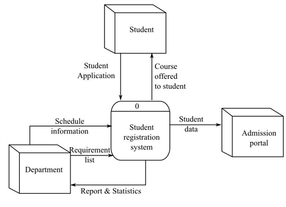
A context diagram in an agile project is a useful technique that a business analyst or product owner / product manager can use. During the product discovery or product inception phase it is important to have a perspective of the context of the product that is to be built and to understand any associated interfaces to the product. A context diagram, sometimes called a level 0 data-flow diagram, is drawn in order to define and clarify the boundaries of the software system.It identifies the flows of information between the system and external entities. The entire software system is shown as a single process.
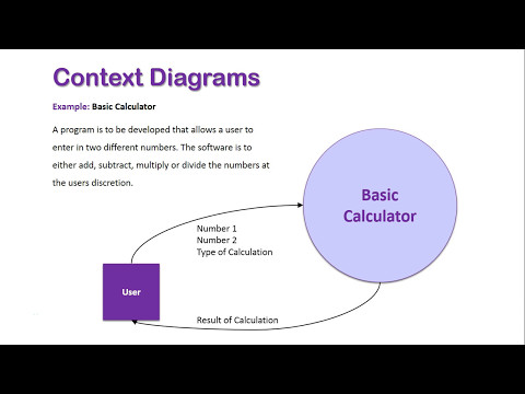
A context diagram is one of the first diagrams you will start creating when you begin looking at software design and development. It is a diagram which will help you define what the problem is that your software is going to solve. It does this by showing who your system will interact with and what data is incolved.

What is context diagram
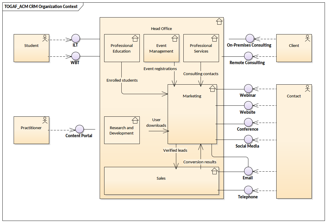
What is a context diagram? A context diagram, sometimes called a level 0 data-flow diagram, is drawn in order to define and clarify the boundaries of the software system. It identifies the flows of information between the system and external entities. The entire software system is shown as a single process. A context diagram is a specialised version of a data flow diagram. System Context Diagrams… represent all external entities that may interact with a system… Such a diagram pictures the system at the center, with no details of its interior structure, surrounded by all its interacting systems, environments and activities. A system context diagram shows components that might be relevant to an architectural design, but it may not explicitly show what this means in terms of problems with the current architecture or improvements delivered by a future architecture. Let’s take an example, summarized in Diagram 1: Architecture Context Diagram.
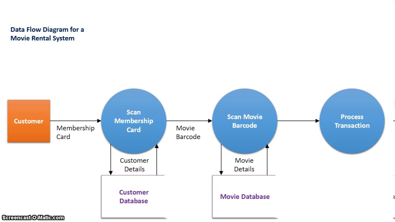
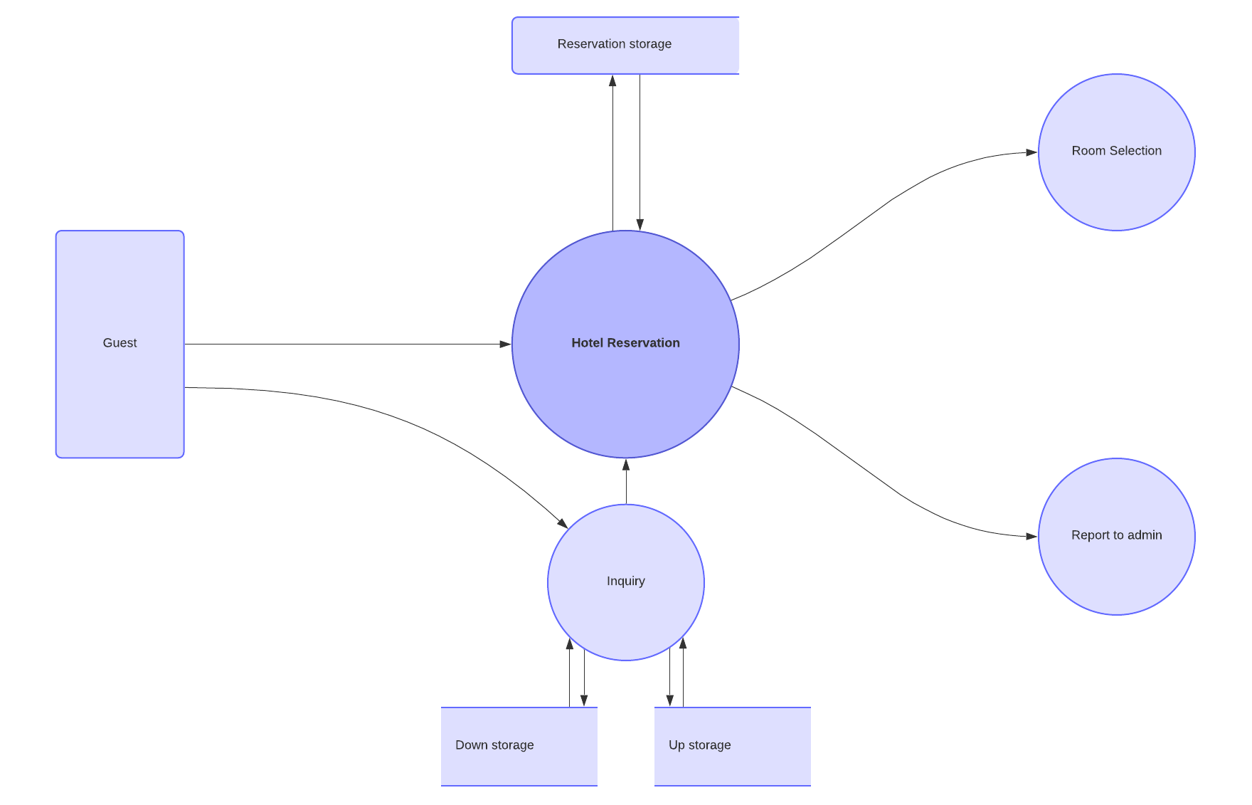
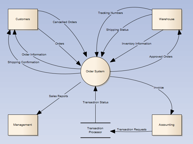
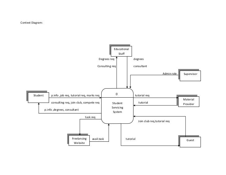
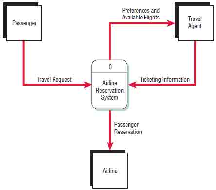
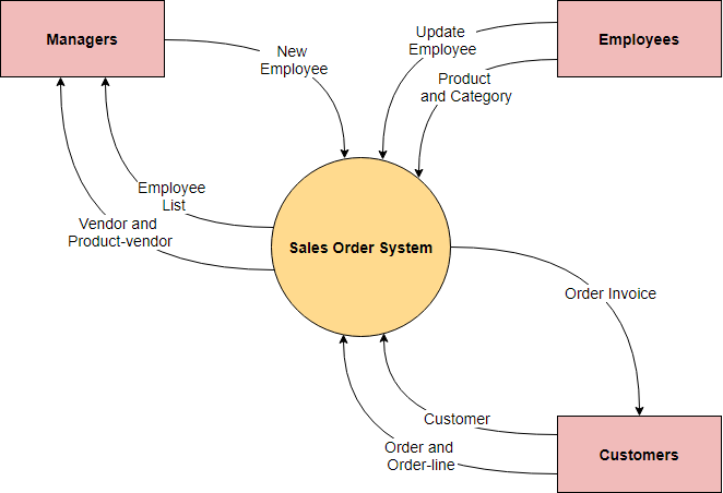
What is context diagram. A data flow diagram (DFD) is a way to show the flow of data through a process or system and the context diagram is a type of DFD. It’s also known as DFD Level 0 because it gives you a quick overview of the system or process being modeled. It’s a high-level design tool meant to define the scope of a project, including its inputs and outputs. The objective of the system context diagram is to focus attention on external factors and events that should be considered in developing a complete set of systems requirements and constraints. A system context diagram is often used early in a project to determine the scope under investigation. Thus, within the document. A system context diagram represents all external entities that may interact with a system. The entire software system is shown as a single process. Such a diagram pictures the system at the center, with no details of its interior structure, surrounded by all its External entities, interacting systems, and environments. Here is an example context diagram for a Sale Order System: Edit this Diagram The context diagram helps you to identify the interfaces you need to account for, helps you to identify scope, identify potential stakeholders, and build a better understanding of the context in which you are working. The context diagram is also known as the context data flow diagram or level 0 data flow diagram. Elements of a context diagram. The Context Diagram shows the system under consideration as a single high-level process and then shows the relationship that the system has with other external entities (systems, organizational groups, external data stores, etc.). Another name for a Context Diagram is a Context-Level Data-Flow Diagram or a Level-0 Data Flow Diagram.
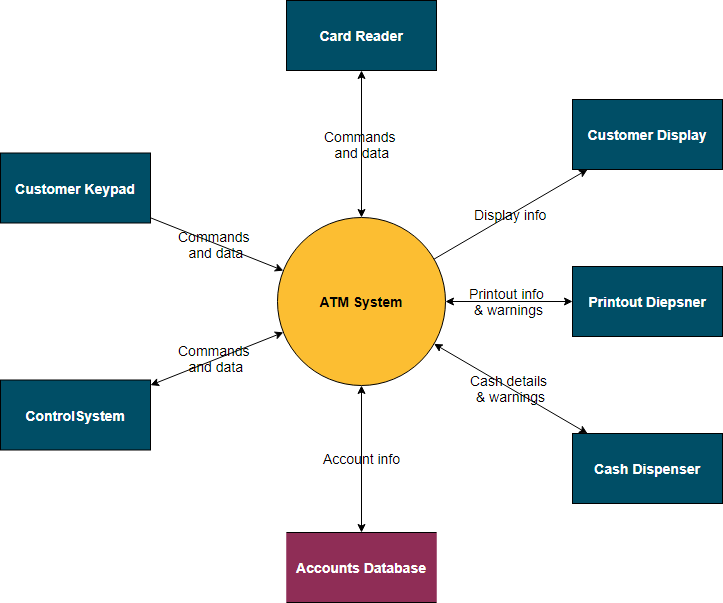
A context diagram, sometimes called a level 0 data-flow diagram, is drawn in order to define and clarify the boundaries of the software system. It identifies the flows of information between the system and external entities. The entire software system is shown as a single process. How do I get a 2 level DFD? The following diagram represents the context switching of two processes, P1 to P2, when an interrupt, I/O needs, or priority-based process occurs in the ready queue of PCB. As we can see in the diagram, initially, the P1 process is running on the CPU to execute its task, and at the same time, another process, P2, is in the ready state. A context diagram is a visual representation of the relationship between data and business processes. This diagram has 3 main components which include external entities, system processes, and data flows. It provides the factors and events you need to consider when developing a system. With it, you will be able to determine the scope, boundaries ... Context diagrams A context diagram is a graphical representation of a system which must only use one process to represent the entire system and deliberately does not go into defining all the processes so as to prevent people getting bogged down in complex details at an early stage. There are only three symbols used in a context diagram:
Context Switching involves storing the context or state of a process so that it can be reloaded when required and execution can be resumed from the same point as earlier. This is a feature of a multitasking operating system and allows a single CPU to be shared by multiple processes. A diagram that demonstrates context switching is as follows −. The context diagram shows the various problem domains in the application domain, their connections, and the Machine and its connections to (some of) the problem domains. Here is what a context diagram looks like. This diagram shows: the machine to be built. The dark border helps to identify the box that represents the Machine. A context diagram, sometimes called a level 0 data-flow diagram, is drawn in order to define and clarify the boundaries of the software system. It identifies the flows of information between the system and external entities. The entire software system is shown as a single process. A system context diagram (SCD) in engineering is a diagram that defines the boundary between the system, or part of a system, and its environment, showing the entities that interact with it. This diagram is a high level view of a system. It is similar to a block diagram . Contents 1 Overview 2 Building blocks 3 Alternatives 4 See also 5 References
Context Diagram Software | Lucidchart
A context diagram makes part of the requirements document in a project. Unlike other project diagrams, the Context diagram is not for use by the engineers/technicians but the project stakeholders. It, therefore, should be laid out in simple and understandable language for easy understanding of the items by the stakeholders when they analyze it.

Data Flow Diagrams
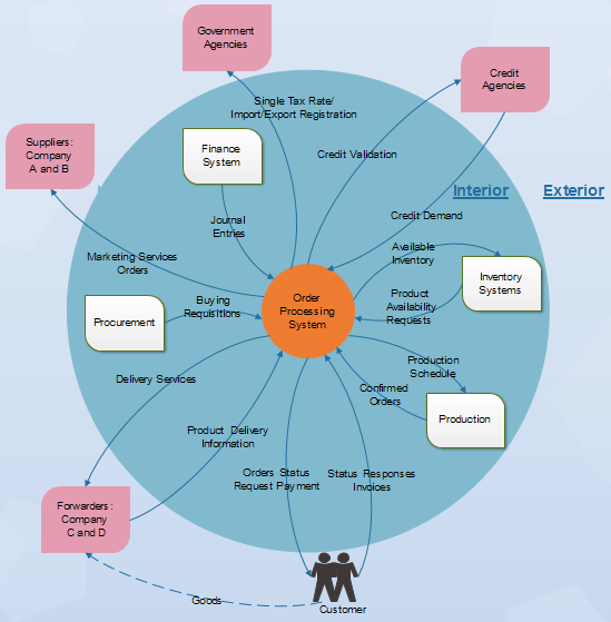
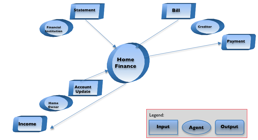
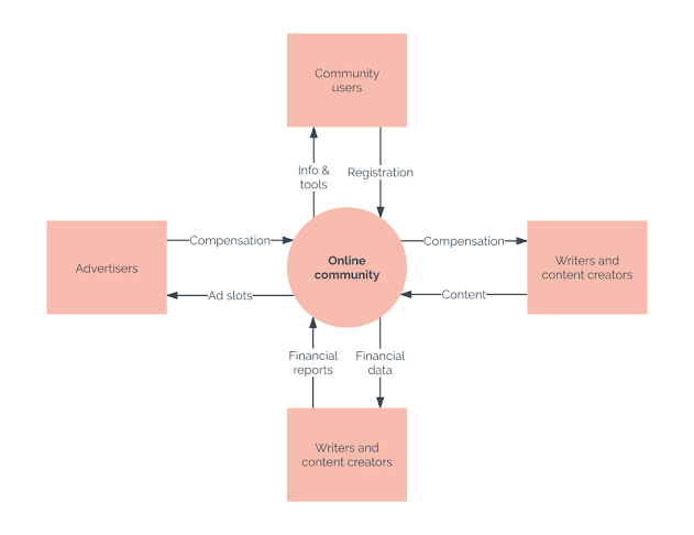
Context diagrams are visual tools that depict the scope of the product showing the business system and how it relates and interacts with the other systems as well. It is a good example of a project management scope model. It shows the inputs to the system, the main players that provide the input as well as the output of the system and the actors receiving them.

Context Diagram 2.4. Data Flow Diagram ( DFD ) Data Flow ...
You can think of a system context diagram as a high-level map of a system and its surrounding environment. Drawing a context diagram helps you to understand how a system interacts with other...
ABC of System Context Diagram | Edraw
Context diagrams are an excellent tool for facilitating brainstorming among those design and analyze them. A context diagram is suitable for noting omissions and blunders in a business plan or project requirements. Hence you can make necessary corrections and adjustments before the project execution and reduce project risks.

What is a system context diagram? (examples) | Gleek
A Context Diagram (sometimes also referred to as a Level-0 Data Flow Diagram) is a common tool that Business Analysts use to understand the context of an entity being examined. Most descriptions of a Context Diagram limit this entity to a system that is being created or modified as part of a project, but the Context Diagram can also be applied ...

Project context diagrams
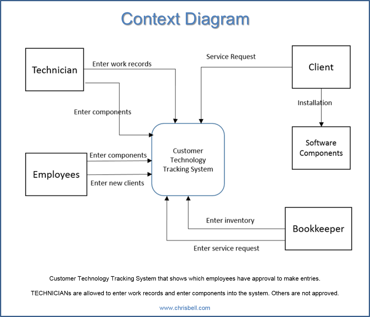
A context diagram is a high-level, informal view of three things: the system you're going to be gathering requirements for, the things that need to interact with the system (use case experts call these things external entities ), and a brief note about the interaction between each thing and the system (#3 is optional).
The Difference Between Context and Data Flow Diagrams
A Context Diagram is also referred to as a Level-0 Data Flow Diagram or a Top-Level Data Flow Diagram. This essentially means that context diagrams can be described in DFD terminology. Level-0 Data Flow Diagrams consist of a single process node and are generally devoid of details about the working of the system.

System context diagram - Wikipedia
The context diagram of a vision document is a simple diagram that shows the source systems contributing data to a DW/BI system, as well as the major user constituents and downstream information systems that is supports. This simple diagram only takes a few minutes to draw once the project architect has completed all the research and the hard thinking that it represents.
Context Diagram -- A Picture That Can Resolve a Thousand ...
Answer (1 of 2): In the UML, a context diagram is used to display how a system relates to its environment (users, related systems, etc.). For example, if I'm working on an order processing application, I might start out with a context diagram. In the middle of the diagram would be a box symboliz...

Context Diagram - an overview | ScienceDirect Topics
A context diagram is a top level (also known as "Level 0") data flow diagram. It only contains one process node ("Process 0") that generalizes the function of the entire system in relationship to external entities. DFD Layers. Draw data flow diagrams can be made in several nested layers. What is a Level 0 diagram?
Event, System, Decomposition, Context and Primitive Diagrams ...
A system context diagram shows components that might be relevant to an architectural design, but it may not explicitly show what this means in terms of problems with the current architecture or improvements delivered by a future architecture. Let’s take an example, summarized in Diagram 1: Architecture Context Diagram.
Chemical Tracking System Context Diagram | System Context ...
A context diagram is a specialised version of a data flow diagram. System Context Diagrams… represent all external entities that may interact with a system… Such a diagram pictures the system at the center, with no details of its interior structure, surrounded by all its interacting systems, environments and activities.

Data Flow Diagrams and Too Much Complexity : r/AskComputerScience
What is a context diagram? A context diagram, sometimes called a level 0 data-flow diagram, is drawn in order to define and clarify the boundaries of the software system. It identifies the flows of information between the system and external entities. The entire software system is shown as a single process.
Data Flow Diagram Symbols, Types, and Tips | Lucidchart

Level 0: Context Diagram
What is A Context Diagram with Examples | EdrawMax Online
Context Diagram | Wiki | BAwiki
Defining The Scope Of Business Analysis With A Context ...
Solved: Draw a context diagram and a diagram 0 DFD that ...
Context Diagram

Requirements Engineer Community - What is "Context Diagram ...
Systems and the Context-Level Data Flow Diagram

Production Cell Context Diagram. | Download Scientific Diagram

System Context Diagram. You can edit this template and create ...

Context Diagram In A Nutshell - FourWeekMBA

Make Context Diagram Online With These Free Websites

IDEF Top-Level Context Diagram Stock Photo - Alamy

The Context of the Work | Mastering the Requirements Process ...

Context diagram of the traceability system. Data flow diagram ...

Context Diagram | Let's think critically about...

Context Diagram
TOGAF Organization Context | Enterprise Architect Diagrams ...

File:Hatley-Pirbhai System Context Diagram.png - Wikimedia ...
What is A Context Diagram with Examples | EdrawMax Online
What is System Context Diagram?
Context Diagram | EdraeMax

A System Context Diagram Example – microTOOL Downloads
Context diagram - How To Discuss
What is System Context Diagram?

Data Flows: Data Flow Diagramming
0 Response to "40 what is context diagram"
Post a Comment