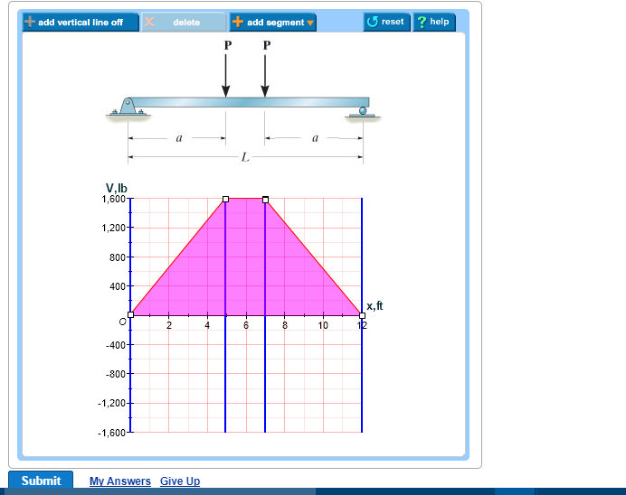
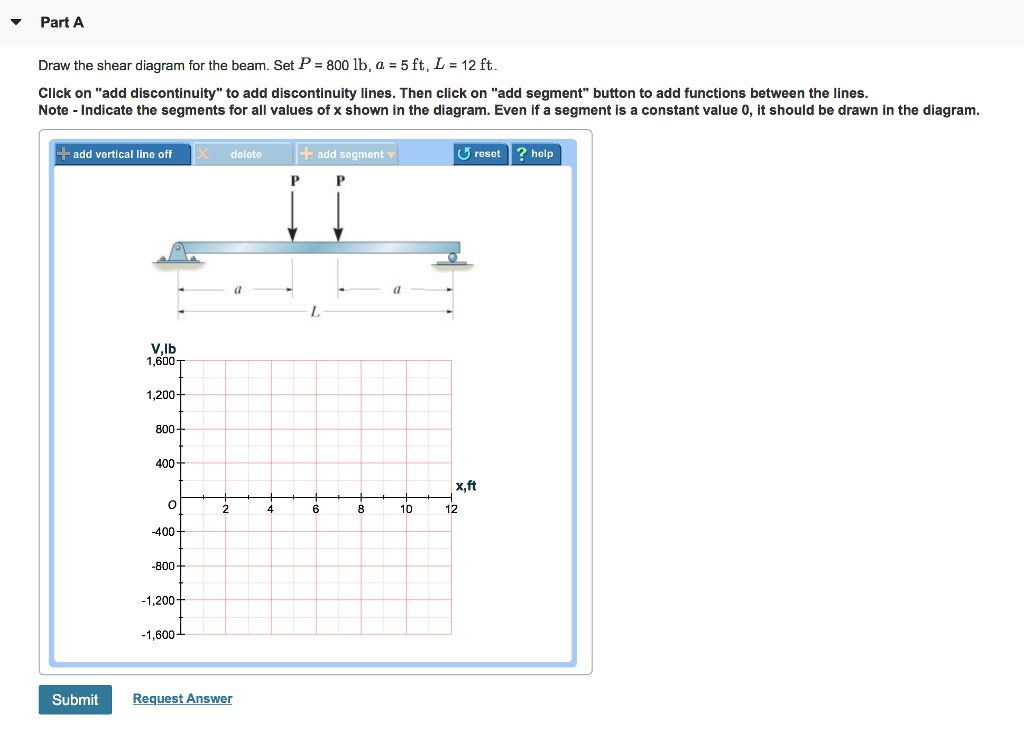
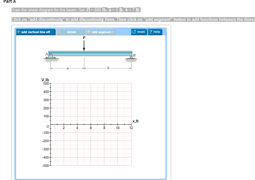
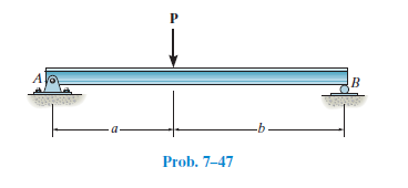
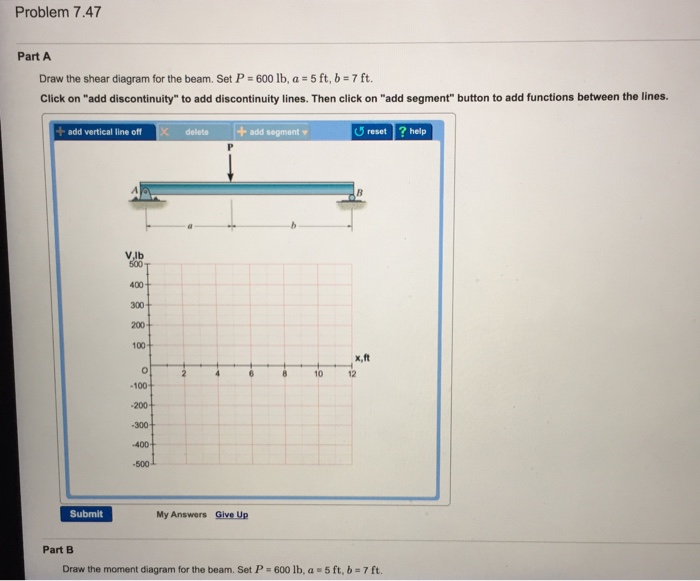
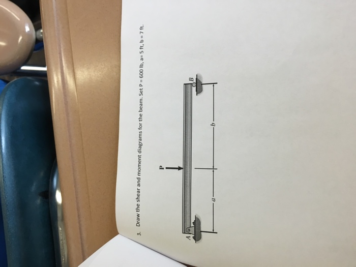
42 draw the shear diagram for the beam. set p = 600 lb, a = 5 ft, b = 7 ft.
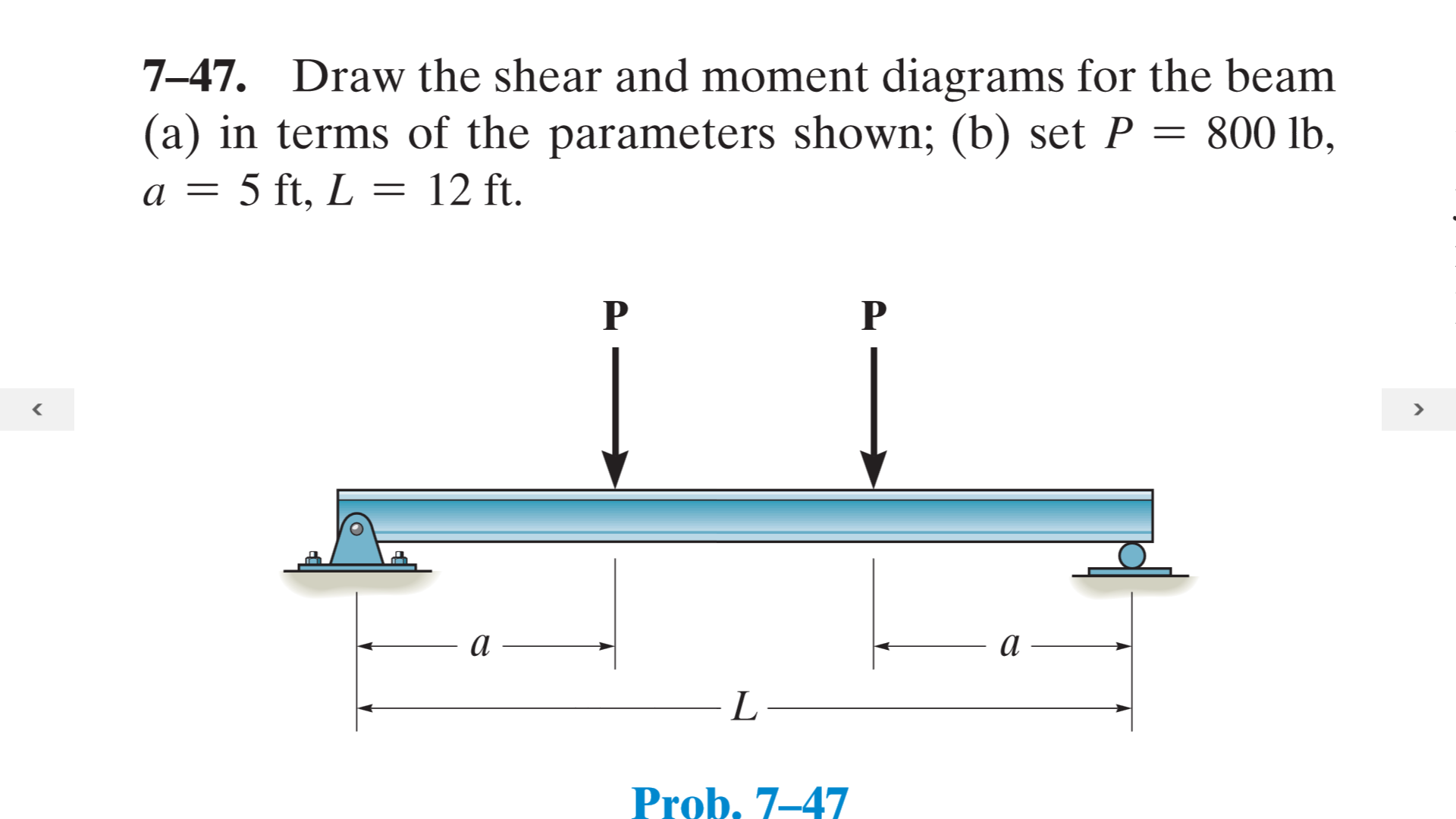
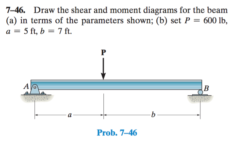
Draw the shear and moment diagrams for the beam (a) in terms of the parameters shown; (b) set P = 600 lb, a = 5 ft, b = 7 ft. 2 | P a g e 2. Draw the shear and moment diagrams for the cantilevered beam. Shear and moment diagrams and formulas are excerpted from the Western Woods Use ... L = span length of the bending member, ft. R = span length of the bending member, in. M = maximum bending moment, in.-lbs. P = total concentrated load, lbs. R = reaction load at bearing ... 7-48 A R 1 Shear a b Figure 25 Beam Fixed at Both Ends–Concentrated ...
in this problem, we have a beam that is simply supported. Honey jam Here there is a point load at the at the middle here and again I because I made the value negative, actually, throughout the arrow positive. And so this point load is at a distance A from the right and left and and then it's at a distance. Be from the right. So if we try to, free by diagram and forces some forces in some ...

Draw the shear diagram for the beam. set p = 600 lb, a = 5 ft, b = 7 ft.
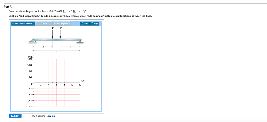
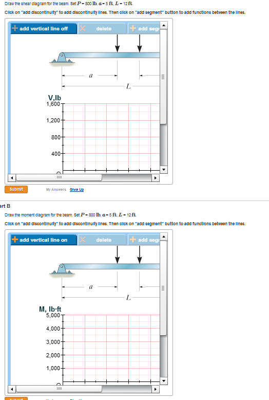
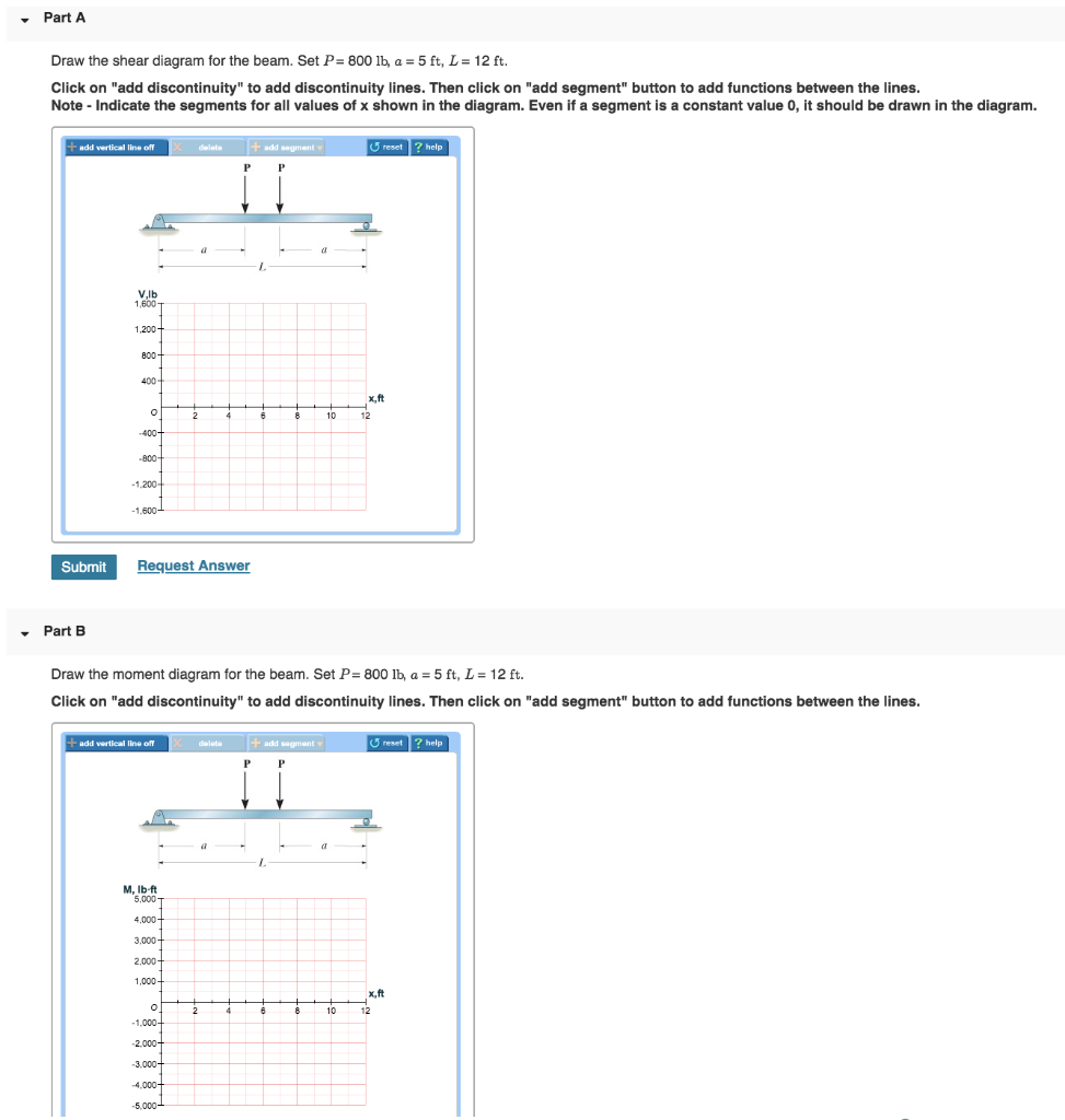
A concentrated load, such as P in Fig. 4.1(a). In contrast a distributed load is applied over a finite area. If the distributed load acts on a very narrow area, the load may be approximated by a line load. The intensity w of this loading is expressed as force per unit length (lb/ft, N/m, etc.) Mechanical Engineering questions and answers. Draw the shear diagram for the beam. Set P = 800 lb, a = 5 ft. L = 12 ft. Click on "add discontinuity" to add discontinuity lines. Then click on "add segment" button to add functions between the lines. Draw the moment diagram for the beam. B. P P. C A. aa. PROBLEM 5. For the beam and loading shown, (a) draw the shear and bending-moment. diagrams, (b) determine the equations of the shear and bending-moment. curves. SOLUTION From A to B: 0 x a FPy 0: V 0. VP MJ 0: Px M 0. M Px From B to C: 2ax a FPy 0: PV 0
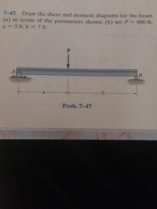
Draw the shear diagram for the beam. set p = 600 lb, a = 5 ft, b = 7 ft.. 6–5. Draw the shear and moment diagrams for the beam. 2 m 3 m 10 kN 8 kN 15 kN m M (kN m) x x ... overhanging beam. 3 ft 3 ft 200 lb/ft 400 lb 6 ft 400 lb A B M (lb ft) x (ft) V (lb) 0 400 0 12 x (ft) 600 1200 1200 300 600 400 3 6 369 12 9 Ans: Hibbeler_Chapter 6_Part 1 (487-517).qxd 2/12/13 11:07 AM Page 499. 510 Transcribed image text: HW 15 Problem 7.47 Part A Draw the shear diagram for the beam. Set P- 600 lb, a 5 ft, b 7ft Click on "add discontinuity" to add ... Transcribed image text: Problem 7.47 Part A Draw the shear diagram for the beam. Set P 600 lb, 5 ft, b 7 ft. Click on "add discontinuity" to add ... Transcribed image text: Draw the shear and moment diagrams for the beam in terms of the parameters shown; set P = 600 lb, a = 5 ft, b = 7 ft.
No portion of this material may be reproduced, in any form or by any means, without permission in writing from the publisher. 7–79. Draw the shear and moment diagrams for the 300 lb 200 lb/ft cantilever beam. Transcribed image text: Draw the shear diagram for the beam. Set P - 600 lb, a = 5 ft, b -7 ft. Click on "add discontinuity" to add discontinuity lines. Transcribed image text: Problem 7.47 Part A Draw the shear diagram for the beam Set P 600 lb, a 5 ft, b ft Click on "add discontinuity" to add discontinuity ... Positive bending moment diagram drawn BELOW the beam SHEAR FORCE & BENDING ... Then, draw the shear force diagram (SFD) and bending moment diagram (BMD). b) If P = 20 kN and L = 6 m, draw the SFD and BMD for the beam. P kN L/2 L/2 A B EXAMPLE 4 . P kN L/2 L/2 R ... then draw the shear force diagram (SFD) and bending moment diagram (BMD). 5 kN/m ...
Question: Draw the shear and moment diagrams for the beam. Set P = 600 lb, a = 5 ft, and b = 7 ft. This problem has been solved! Set P = 600 lb. a = 5 ft. b = 7 ft Click on add discontinuity to add discontinuity lines. Then click on add segment button to add functions between the lines ... Transcribed image text: Draw the shear and moment diagrams for the beam (a) in terms of the parameters shown; (b) set P-600 lb, a-5 ft, b-7 ft. Set P = 600 lb, a = 5 ft, b = 7 ft. Click on "add discontinuity" to add discontinuity lines. Then click on "add segment" button to add functions between the ...
Transcribed image text: Part A Draw the shear diagram for the beam. Set P = 600 lb, a = 5 ft, b = 7 ft. Click on "add discontinuity" to add discontinuity lines. Then click on "add segment" button to add functions between the lines. + + O @ b No elements selected V, lb 500 400 300 200 100 2, ft 0+ 0 -100- 2 4 6 8 10 12 -200 -300 -400 -500 Part B Draw the moment diagram for the beam.
Question: draw the shear and moment diagram for the beam (a) in terms of the parameters shown; (b) set P= 600lb, a=5ft, b=7ft ...
B. P P. C A. aa. PROBLEM 5. For the beam and loading shown, (a) draw the shear and bending-moment. diagrams, (b) determine the equations of the shear and bending-moment. curves. SOLUTION From A to B: 0 x a FPy 0: V 0. VP MJ 0: Px M 0. M Px From B to C: 2ax a FPy 0: PV 0
Mechanical Engineering questions and answers. Draw the shear diagram for the beam. Set P = 800 lb, a = 5 ft. L = 12 ft. Click on "add discontinuity" to add discontinuity lines. Then click on "add segment" button to add functions between the lines. Draw the moment diagram for the beam.
A concentrated load, such as P in Fig. 4.1(a). In contrast a distributed load is applied over a finite area. If the distributed load acts on a very narrow area, the load may be approximated by a line load. The intensity w of this loading is expressed as force per unit length (lb/ft, N/m, etc.)





![Solved: 5. [7-46] Draw The Shear And Moment Diagrams For T ...](https://d2vlcm61l7u1fs.cloudfront.net/media%2Fcb1%2Fcb181ecc-92fa-4650-af18-4b3859cffef4%2Fphp3Gr26R.png)






0 Response to "42 draw the shear diagram for the beam. set p = 600 lb, a = 5 ft, b = 7 ft."
Post a Comment