45 baldor motors wiring diagram
Does anybody know which wires correlate to which features on the bafang hub motors? Doing some surgery here and I’m just trying to pinpoint which wires are responsible for the direction of the motor rotation. Also how to reverse the rotation if needed Thanks! Large Stock & Expert Service for all Styles & Sizes of V-Belt Pulleys/Sheavs. Fast Response & Same Day Shipping. Call 866-354-0063 - Online V-Belt Drives Catalog
Does anyone know of a wiring diagram of the stock Rhino Fire harness? I'm curious what some of these small boards and the switch behind the left side Scotch yoke are used to control/sense. I'd also like to replace the flywheel motors, but it seems none of the dual-shaft motors I found have long enough output shafts to make it work. I noticed that a few people have made conversions to 4-motor 2-cage setups, but I'm trying to do this relatively simply since it's going to be stock performance, I ...
Baldor motors wiring diagram
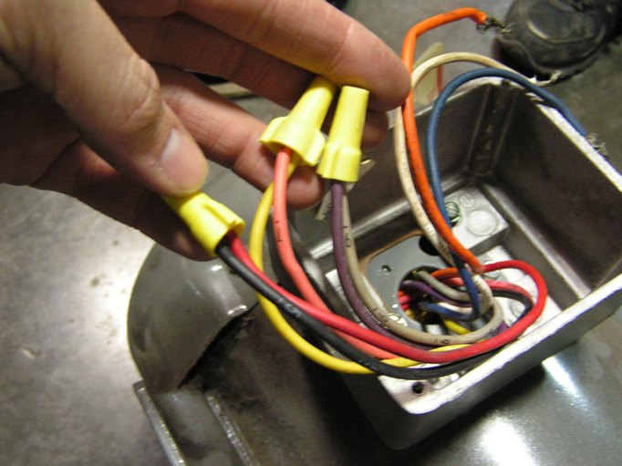
13 steps1.Check power source. Ensure that any electrical power fed into power cord, is shut off prior to working on motor.2.Prepare power cord. Using a pair of diagonal cutters, cut and remove 3 in of rubber insulation around outside of power cord. Revealing four wires inside cord. Remove approx. 3 inches (7.6 cm) of insulation from the outside of the four lines located within the power cord. Once for inner lines are visible remove approx. 1in. of insulation from the red, white and black lines, revealing copper wire. Be aware that the power lines are referred to as: L1, L2, L3 respectively however there is no specific order to the power lines, meaning these tittles can be used interchangeably.3.Connect ground wire to wire terminal. Using a crimping tool, connect ring terminal to the end of ground (green) wire. I am rewiring a machine that I bought used. The original owner made extensions that were not color coded and I messed up and cut the cable before labeling each lead. My motors have a red, blue, green and black wire I believe. I just need to know how to wire them into the molex connector. Thanks!! Click to get the latest Where Are They Now? content.
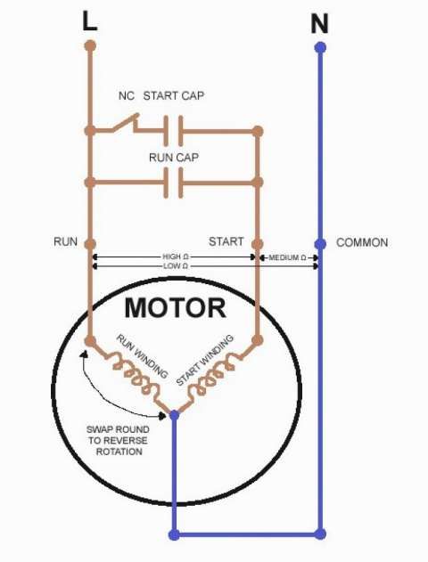
Baldor motors wiring diagram. Does anyone know where I can find a complete wiring diagram for the E5 with a 4.2.7 Board? Long story short I switched some wires around in the extruder cable trying to fix things, got mixed up, and fried my board. Now I can't rememebr which way the wires were supposed to go and I can't seem to find a diagram for it online. If anyone can point me in the right direction I would really appreciate it. 26.10.2018 · 120v Ac Capacitor Motor Reversing Switch Wiring Diagram 26.10.2018 26.10.2018 0 Comments on 120v Ac Capacitor Motor Reversing Switch Wiring Diagram To complete a single phase motor direction change, you will need to motors go in forward and reverse depending on their wiring and the resulting magnetic field. ​ [T9 connects from SINPAC switch to ?](https://preview.redd.it/ftdgzxh6b4c81.jpg?width=1057&format=pjpg&auto=webp&s=5c10b64d8c1a0cab95ecdeb687d971c9cea07578) Can someone confirm that this diagram will work to wire up my tank https://imgur.com/gallery/oClOQbp
11.01.2022 · Obituary for William Muir. Welcome to VintageMachinery.org Knowledge Base (Wiki)! The VM Knowledge Base is a wiki based tool for topics related to the use and restoration of vintage metalworking & woodworking machinery, electric … Hi - I have a older GE motor #5KC49BB514EX. I'm trying to find out the year it was made and also a wiring diagram. The second picture shows the wiring box - if that's what you call it. On the top right, there is a red (bare) wire coming out of the motor housing. On the bottom left there is a black wire with tape coming out of the housing. There are 4 terminals from the top 1 through 4. Any help would be great. Thanks Hello. Anybody here who knows or has a wiring diagram for a Coswheel FTN T20 ebike? I need help on how to rewire and add turn signal lights on the front and back. It has already the turn switch on the handle bar. Just need to know where the wires to connected or it's a plug and play. The bike has a 500 watts rear hub motor and a 48 volts 15 ah battery. Any help is much appreciated. Thanks all. Wondering if someone could post a wiring diagram for the Mantis 10 Elite as I finished replacing a damage disc brake rotor and ive wired the front wheel wrong and now it spins backwards 😂 Since I’d rather not just unplugged it and try something different I’d prefer to look at the diagram and fix it correctly Thanks
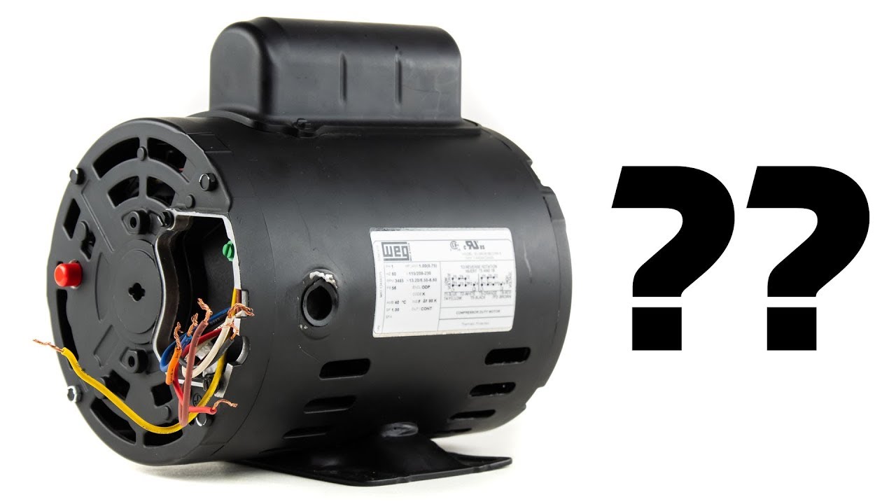
Jan 21, 2021 — The manufacturer of these products, Baldor Electric Company became ABB ... Motor and control wiring, overload protection, disconnects, ...36 pages http://imgur.com/a/RHFodBY I have a Baldor motor I can't find the specs for. It's for a Felker Tile Master saw. I need to figure out how to wire it. It was running when it was removed. * 35S367Q047G1 * single phase * 1.5 HP * 115/230V It has 5 wires, two of which I know go to the start/run capacitor (they were marked). This leaves a brown, white/yellow, and blue wire. Resistance is BR->WY 2 ohm, BR->BL 1.1 Ohm, WY->BL 2 Ohm. Thank you for your help. Click to get the latest Where Are They Now? content.
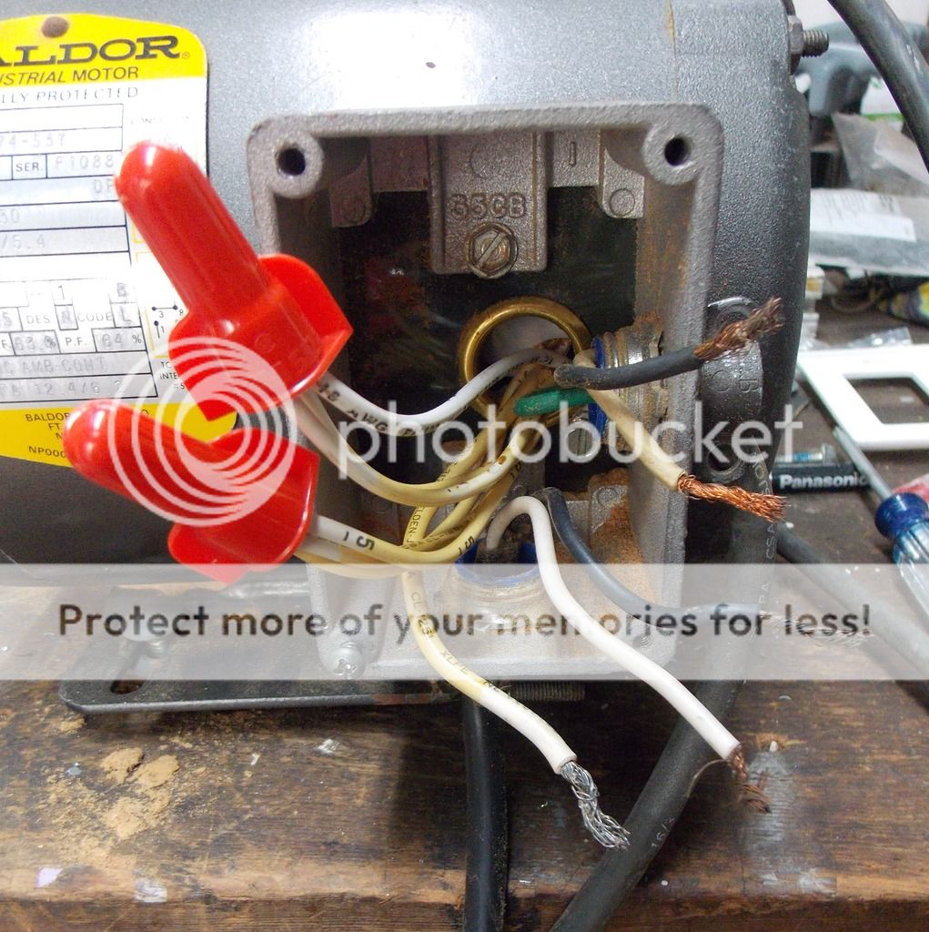
Reversing the direction of the 3HP Baldor motor
I am rewiring a machine that I bought used. The original owner made extensions that were not color coded and I messed up and cut the cable before labeling each lead. My motors have a red, blue, green and black wire I believe. I just need to know how to wire them into the molex connector. Thanks!!

Diagram based baldor single phase motor capacitor wiring ...
13 steps1.Check power source. Ensure that any electrical power fed into power cord, is shut off prior to working on motor.2.Prepare power cord. Using a pair of diagonal cutters, cut and remove 3 in of rubber insulation around outside of power cord. Revealing four wires inside cord. Remove approx. 3 inches (7.6 cm) of insulation from the outside of the four lines located within the power cord. Once for inner lines are visible remove approx. 1in. of insulation from the red, white and black lines, revealing copper wire. Be aware that the power lines are referred to as: L1, L2, L3 respectively however there is no specific order to the power lines, meaning these tittles can be used interchangeably.3.Connect ground wire to wire terminal. Using a crimping tool, connect ring terminal to the end of ground (green) wire.
Baldor motor wiring | The Hobby-Machinist

12+ Baldor Electric Motor Capacitor Wiring Diagram - Wiring ...

Practical Machinist - Largest Manufacturing Technology Forum ...

Weg Motor Capacitor Wiring Diagrams Schematics and Baldor ...
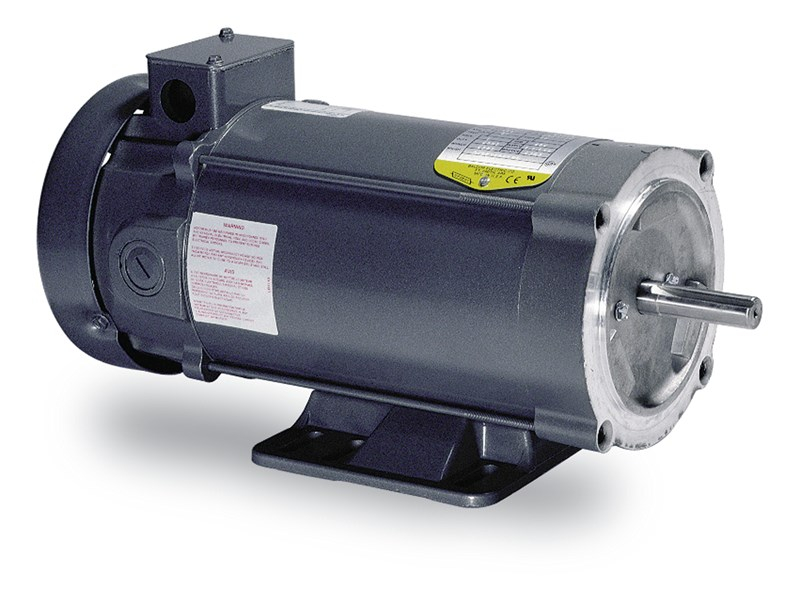
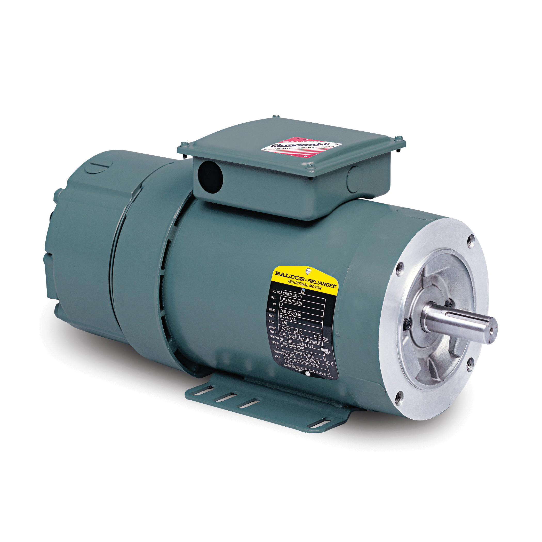
Baldor, CD3476, .75HP, General Purpose Motor
All about Baldor Single Phase Motor Wiring Diagram
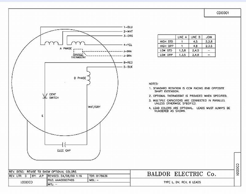
![Baldor Industrial Motor wiring diagram [Automotive industry]](http://www.ubmtechweb.co.uk//img/baldor_motor_wiring_diagram_wiring.jpg)
Baldor Industrial Motor wiring diagram [Automotive industry]

AIM Manual - Page 57 | Single-Phase Motors and Controls ...

BALDOR L1410T MOTOR PARTS CAPACITOR BOX KIT COMPRESSOR PARTS ...

ABB Baldor FDL3731M 5HP, 1740RPM, 1PH, 60HZ, 215, 3730LC, TEFC, F1

Baldor Motor Capacitor Wiring | The Garage Journal

Practical Machinist - Largest Manufacturing Technology Forum ...
3 capacitor 240v motor, how to hook up capacitors? On ...
Single Phase Electric Motor Wiring Tutorial: Baldor, WEG, Leeson

Wiring Capacitors for Baldor VL1309 Air Compressor Motor ...

love wallpaper: baldor wiring diagram

FDL3737TM - Product Catalog - Baldor.com
PM66 Baldor 3HP motor wiring - need connection info ...

Wiring Diagram For 220 Volt Single Phase Motor, http ...
L1408TM Baldor Single Phase Open Foot Mounted 3HP, 1725RPM ...
L1408T Baldor Single Phase Open Foot Mounted 3HP, 1725RPM ...

Baldor CL3510 General Purpose AC Motor, Single Phase, 56C Frame, TEFC Enclosure, 1Hp Output, 1725rpm, 60Hz, 115/230V Voltage

Baldor Industrial Motor VM3116, 1 HP, 230/460 V, 3.4/1.7 A, 1725 RPM, Frame 56C, 60 Hz, 3 PH

ABB Baldor EM7090T-I 100/75HP, 1780/1485RPM, 3PH, 60/50HZ, 405

How do I wire a motor reversing switch on this Baldor motor ...

Baldor Reliance Industrial Motor Wiring Diagram Gallery ...
Brake Connection Diagram

Baldor Motor: Baldor FDL3737TM Specs and Crossovers

I have an air compressor that I acquired that I am changing ...

12+ Baldor Electric Motor Capacitor Wiring Diagram - Wiring ...
12+ Baldor Electric Motor Capacitor Wiring Diagram - Wiring ...
.jpg)
I HAVE A PROBLEM WITH MY MOTOR CAPACITORS I HAVE A BALDOR ...

How to: Connect a 3 Phase Baldor Motor Ver. 2
Baldor-Reliance VEBM3611T-D | B&D Industrial
7 1/2 HP 3 Phase Baldor Motor?

Need wiring diagram for Baldor 1hp, single Phase motor.

Sawmill Creek Woodworking Community

I'm just searching for some type of proper wiring for the ...

Ideas Collection Baldor Wiring Diagram New Baldor Wiring ...

CL3608TM - Product Catalog - Baldor.com

Baldor Motor Wiring Diagrams Single Phase | Electrical wiring ...

Baldor 3HP Motor Test

22 Stunning Electrical Switch Wiring Diagram - bacamajalah ...
0 Response to "45 baldor motors wiring diagram"
Post a Comment