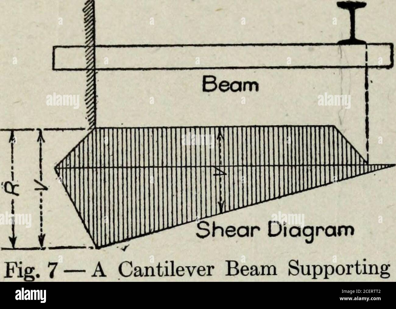
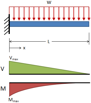
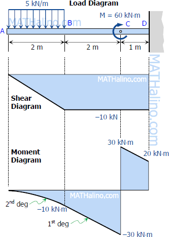
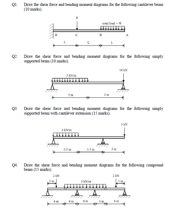
44 moment diagram for cantilever beam
PDF Beam Diagrams and Formulas BEAM DIAGRAMS AND FORMULAS 3-219 Table 3-23 (continued) Shears, Moments and Deflections 18. CANTILEVERED BEAM- LOAD INCREASING UNIFORMLY TO FIXED END Draw the shear and moment diagram of common beam | Chegg.com Civil Engineering. Civil Engineering questions and answers. Draw the shear and moment diagram of common beam design: (a) Cantilever (b) Simply supported (c) Overhanging (d) continuous (e) Fixed ended 220 (1) Cantilever, simply supported.
Cantilever Beam | SkyCiv Engineering Cantilever Beam Equations (Deflection) Taken from our beam deflection formula and equation page: Sample Cantilever Beam equations can be calculated from the following formula, where: W = Load. L = Member Length. E = Young's Modulus. I = the beam's Moment of Inertia.
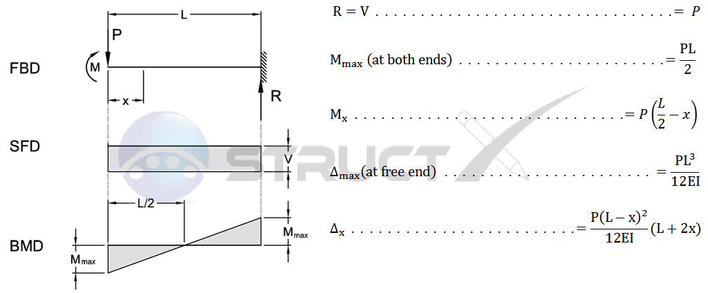
Moment diagram for cantilever beam
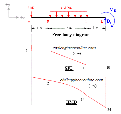
Shear Force and Bending Moment Diagram for Cantilever Beam ... Case 01. Shear Force and Bending Moment Diagram of Cantilever beam when point load is applied. From the figure we have the value of load at point A and point B. So let’s draws the shear force diagram with the help of these loading. Bending moment at point A is zero. Bending moment at point B= -2*2 = 4 KN-M. Bending moment at point C= -2*4-4*2 = 12 KN-M. Cantilever Beam | Advantages of a Cantilever Beam ... Shear Force and Bending Moment Diagram for Cantilever Beam with Point Load at the Free End L is the length shown in Fig when a point is a fixed end when point b is the free end. For calculation of shear force. Suppose the x-x section is the distance from a point B to x. So the shear force on the x-x section. Fx = + W. The shear force at point A, Shear Force and bending moment diagram - ExtruDesign Shear force and Bending moment Diagram for a Cantilever beam with a Point load at the free end. Shear force and Bending moment Diagram for a Cantilever beam with a Uniformly distributed load. SFD and BMD for a Cantilever beam with a Uniformly varying load. Reference: Textbook of Strength of Materials by Rk Bansal.
Moment diagram for cantilever beam. Cantilever Beam - UDL and End Bending Moment The above beam design and deflection equations may be used with both imperial and metric units. As with all calculations/formulas care must be taken to keep consistent units throughout with examples of units which should be adopted listed below: Notation. FBD = free body diagram; SFD = shear force diagram; BMD = bending moment diagram Shear Force & Bending Moment Diagram of Cantilever Beam ... Oct 15, 2014 · This shows shear force is maximum at fixed end and minimum at free end of cantilever beam. Shear Force Diagram. Bending Moment. Bending moment at point D = B.M (D) = 0. Bending moment at point C = B.M (C) = -(100×1) = -100 kg.m. Bending moment at point B = B.M (B) = – (100×2 +200×1) B.M (B) = -400 kg.m. Bending moment at point A = B.M (A) = (100×3 + 200×2 + 300×1) Total Moment at point A = B.M (A) = -1000 kg.m Shear Force & Bending Moment diagram for Cantilever Beam ... This video shows the shear force and bending moment diagram for a cantilever beam. Cantilever is the type of beam having fixed support at one end and free at... Shear Force and Bending Moment Diagram for Cantilever Beam ... Generally, in the case of cantilevers, the shear force and the bending moment will be maximum at the supports. In this case the shear force is constant throughout the length of the cantilever. Maximum S.F = +W = +12kN Cantilever beam shear force diagram Maximum B.M = -WL = -12 x 4 = -48kN.m Result: Max S.F = +12kN (constant throughout the length)
Draw the shear and moment diagrams for the cantilevered beam Calculate the moment at A as follows: Take moment about point A. The cantilever support has 3 reactions. The upward force is considered a positive and downward force is considered as negative. The clockwise moment is considered a positive and anticlockwise moment is considered as negative. Step 2 of 3 Calculate the shear force at various lengths. The moment diagram for a cantilever beam subjected to ... The moment diagram for a cantilever beam subjected to bending moment at end of beam will bea)cubic parabolab)rectanglec)triangled)ellipticalCorrect answer is option 'B'. Can you explain this answer? | EduRev Mechanical Engineering Question Mechanical Engineering Question PDF 4. Bending Moment and Shear Force Diagram Chapter-4 Bending Moment and Shear Force Diagram S K Mondal's Maximum bending moment, 2 max wL 2 M at fixed end Another way to describe a cantilever beam with uniformly distributed load (UDL) over it's whole length. (iii) A Cantilever beam loaded as shown below draw its S.F and B.M diagram In the region 0 < x < a Cantilever Beam - Point Load and Bending Moment at Free End Cantilever Beam - Point Load Free to Deflect Vertically with No RotationMore Beams. Max. Moment, M max: The above beam deflection and resultant force calculator is based on the provided equations and does not account for all mathematical and beam theory limitations. The calculator has been provided with educational purposes in mind and should ...
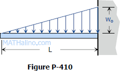
Cantilever Beam Deflection Calculator A cantilever beam will have moment reaction at both ends to be 0 and will have vertical reactions at both ends. Slope at both end will not be 0. Cantilever beam with udl on entire span formula Cantilever beam with udl Parameter Values Moment at A M_ {A}=\frac {w* L^ {2}} {2} M A = 2w∗L2 Reaction at A V_ {A}=\left (w * L\right) V A = (w ∗ L) shear force and bending moment diagram for cantilever beam ... #civilengineering #som Solution to Problem 410 | Shear and Moment Diagrams ... Problem 410 Cantilever beam carrying the uniformly varying load shown in Fig. P-410. [collapse collapsed title="Click here to read or hide the general instruction"]Write shear and moment equations for the beams in the following problems. In each problem, let x be the distance measured from left end of the beam. Also, draw shear and moment diagrams, specifying values at all Moment area method for beam deflections : article ... is constant throughout the beam, the first moment area theorem can be formulated in the following expression: where , the x coordinates of points 1 and 2. The integral is the area of the bending moment diagram between points 1 and 2. In many cases, the area can be found analytically, avoiding integration completely. Theorem 2
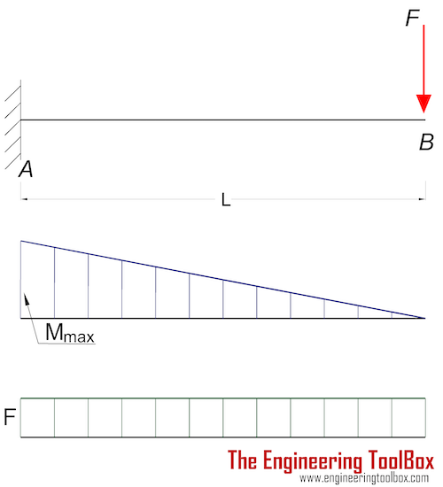
Cantilever Beams - Moments and Deflections Cantilever Beam - Single Load at the End Maximum Reaction Force at the fixed end can be expressed as: RA = F (1a) where RA = reaction force in A (N, lb) F = single acting force in B (N, lb) Maximum Moment at the fixed end can be expressed as Mmax = MA = - F L (1b) where MA = maximum moment in A (Nm, Nmm, lb in) L = length of beam (m, mm, in)
What is the moment of cantilever beam? - Morethingsjapanese What is the moment of cantilever beam? In a cantilever beam, shear force at any section is equal to the sum of the loads between the sections and the free end. Bending moment at a given section is equal to the sum of the moments about the section of all the loads between the section and the free end of the cantilever.
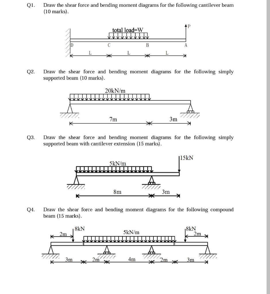
PDF Beam Design Formulas With Shear and Moment and moment diagrams with accompanying formulas for design of beams under various static loading conditions. Shear and moment diagrams and formulas are excerpted from the Western Woods Use Book, 4th edition, and are provided herein as a courtesy of Western Wood Products Association. Introduction Notations Relative to "Shear and Moment Diagrams"
Free Online Beam Calculator for Cantilever or ... - SkyCiv Free online beam calculator for generating the reactions, calculating the deflection of a steel or wood beam, drawing the shear and moment diagrams for the beam. This is the free version of our full SkyCiv Beam Software. This can be accessed under any of our Paid Accounts, which also includes a full structural analysis software.
[Solved] The Bending Moment Diagram of a cantilever beam ... For a cantilever beam as shown in figure, find the Bending Moment at A. Q6. If a simply supported beam of 6 m span carries a point load of 50 kN at center, calculate the value of Reaction forces.
Draw Bending Moment & Shear Force Diagrams - Cantilever Beam This video explains how to draw shear force diagram and bending moment diagram with easy steps for a cantilever beam loaded with a concentrated load. Shear f...
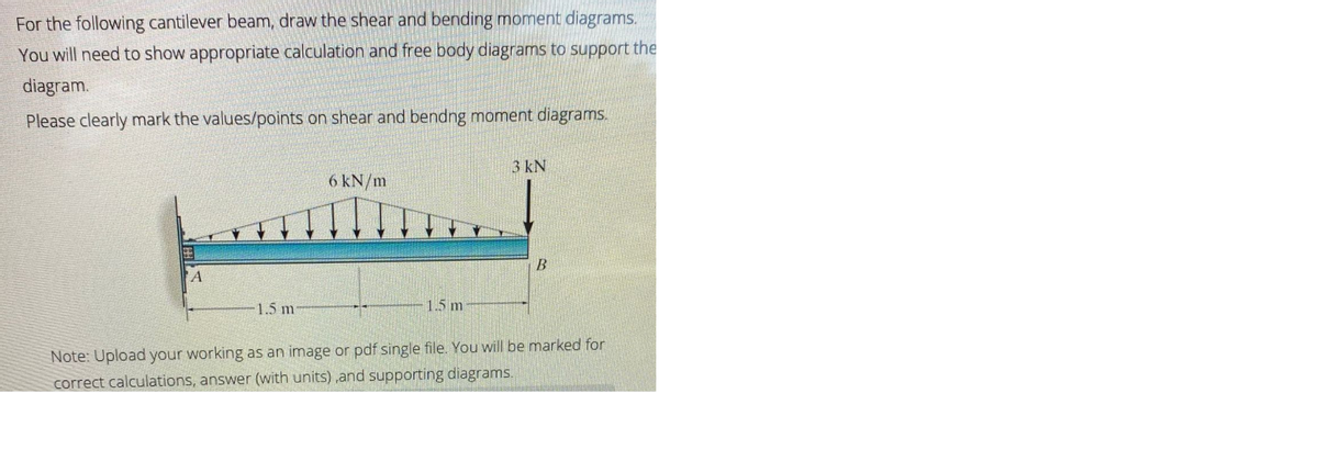
Answered: Draw the shear and moment diagrams for… | bartleby Transcribed Image Text: Draw the shear and moment diagrams for the cantilever beam shown and determine the maximum absolute value of the shear and bending moment. Indicate the degree of each curve. You may use the method of sections, area method, or both. 15 kN/m 8 kN 5 kN/m A В 20 kN/m 8 kN/m E 2 m →e 3 m 6 m. Expert Solution.
2.1.2 Analysis of Shear and Moment of UDL on Cantilever ... 3/9/22, 6:55 PM 2.1.2 Analysis of Shear and Moment of UDL on Cantilever beam: ARSC 433-ARCH41S1 - Steel and Timber Design 1/5 2.1.2 Analysis of Shear and Moment of UDL on Cantilever beam Sample problem: A Cantilever beam with a loading (W) of 12 Kn / m is uniformly distributed throughout its entire length, plot the shear and moment diagram if the length of the beam is 3 meters.
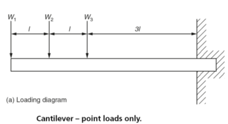
PDF Module -4 Shear Force and Bending Moment Diagrams Variation of shear force and bending moment diagrams S.N Point Load UDL UVL Shear Force Constant Linear Parabolic Bending Moment Linear parabolic Cubic WORKED EXAMPLES 1) A cantilever beam of length 2 m carries the point loads as shown in Fig. Draw the shear force and B.M. diagrams for the cantilever beam. Shear Force Diagram S.F. at D, F D
Draw the shear and moment diagrams for the cantilever beam ... Draw the shear and moment diagrams for the cantilever beam. Results. See All Results. Question: Mechanics of Materials - Instructor Solutions Manual [EXP-4667] Draw the shear and moment diagrams for the cantilever beam. Step-by-Step. Report Solution. Verified Solution.
Bending moment and shear force diagram of a cantilever beam Sep 11, 2017 · BENDING MOMENT AND SHEAR FORCE DIAGRAMS OF A CANTILEVER BEAM. A shear force diagram is the graphical representation of the variation of shear force along the length of the beam and is abbreviated as S.F.D. A bending moment diagram is the graphical representation of the variation of he bending moment along the length of the beam and is abbreviated as B.M.D.
Shear Force and bending moment diagram - ExtruDesign Shear force and Bending moment Diagram for a Cantilever beam with a Point load at the free end. Shear force and Bending moment Diagram for a Cantilever beam with a Uniformly distributed load. SFD and BMD for a Cantilever beam with a Uniformly varying load. Reference: Textbook of Strength of Materials by Rk Bansal.
Cantilever Beam | Advantages of a Cantilever Beam ... Shear Force and Bending Moment Diagram for Cantilever Beam with Point Load at the Free End L is the length shown in Fig when a point is a fixed end when point b is the free end. For calculation of shear force. Suppose the x-x section is the distance from a point B to x. So the shear force on the x-x section. Fx = + W. The shear force at point A,
Shear Force and Bending Moment Diagram for Cantilever Beam ... Case 01. Shear Force and Bending Moment Diagram of Cantilever beam when point load is applied. From the figure we have the value of load at point A and point B. So let’s draws the shear force diagram with the help of these loading. Bending moment at point A is zero. Bending moment at point B= -2*2 = 4 KN-M. Bending moment at point C= -2*4-4*2 = 12 KN-M.

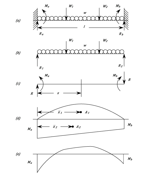











![Cantilever Beam: Shear Force and Bending Moment Diagram [SFD BMD Problem 2] By Shubham Kola | Facebook](https://lookaside.fbsbx.com/lookaside/crawler/media/?media_id=257535155732524&get_thumbnail=1)


0 Response to "44 moment diagram for cantilever beam"
Post a Comment