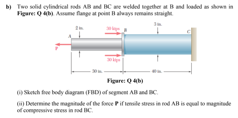
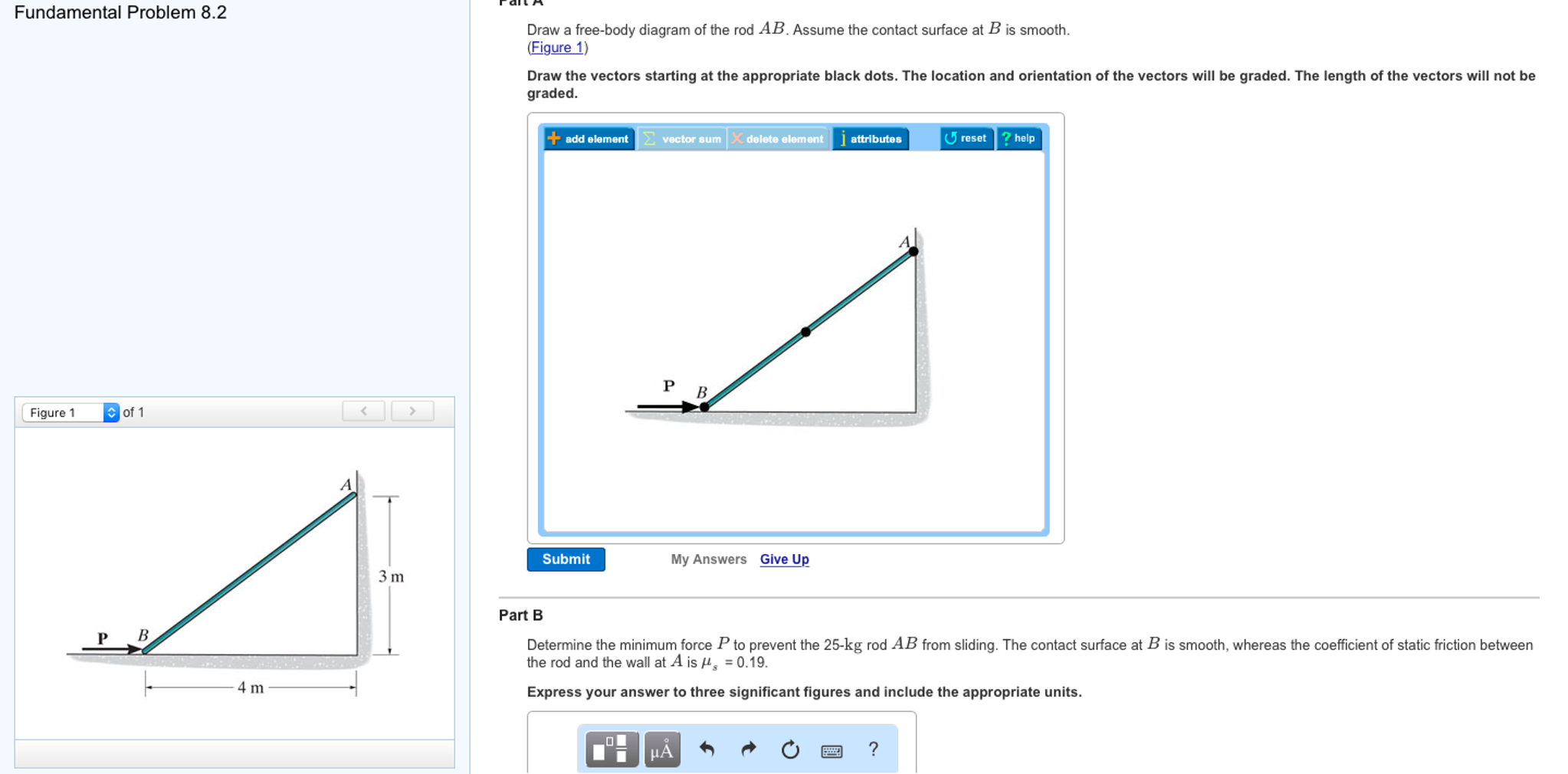
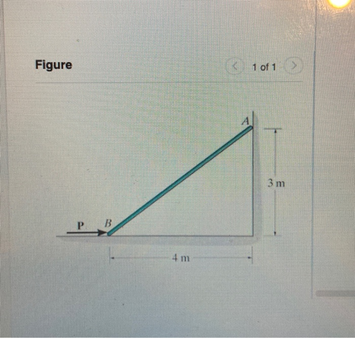
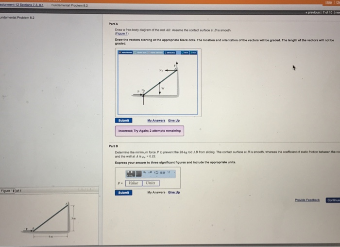
41 draw a free-body diagram of the rod ab. assume the contact surface at b is smooth.
p.216, 5-9. Draw the free-body diagram of the beam, which is pin- ... smooth surface and an equal portion of the load is supported at both the front and rear tires. 5-32. ... components of reaction at the pin C and the force developed in rod AB on the crane when x = 5 m. 5-34. 5-35 p.235, 5-60. The uniform rod has a length l and weight W. It is ... Determine the minimum force P to prevent the 24-kg rod AB from sliding. The contact surface at B is smooth,. This problem has been solved! See the answer ...
Draw a free body diagram accounting for all external forces and couples. Show the resulting inertia forces and couple (typically on a separate kinetic diagram). 3. Compute the mass moment of inertia I G or I O. 5. Use kinematics if there are more than three unknowns (since the equations of ...
Draw a free-body diagram of the rod ab. assume the contact surface at b is smooth.
Assume the contact surface at B is smooth. Draw the vectors starting at the appropriate black dots. The location and orientation of the vectors will be graded. FREE-BODY DIAGRAMS (Section 5.2) 2. Show all the external forces and couple moments. These typically include: a) applied loads, b) support reactions, and, c) the weight of the body. Idealized model Free-body diagram (FBD) 1. Draw an outlined shape. Imagine the body to be isolated or cut "free" from its constraints and draw its outlined shape. Draw the free-body diagram of the bar, which has a 75 3mm in. negligible thickness and smooth points of contact at A, B, 30 and C. Explain the significance of each force on the 5 in.mm 125 diagram. (See Fig. 5–7b.)
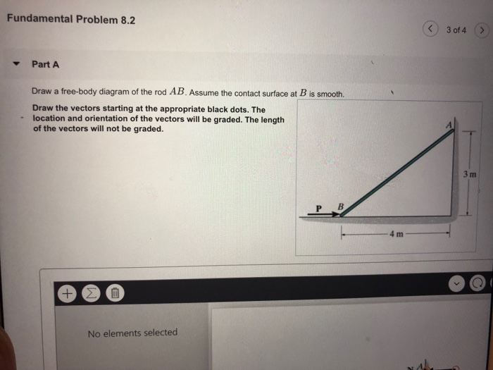
Draw a free-body diagram of the rod ab. assume the contact surface at b is smooth.. Book: http://amzn.to/2i8HBOOMore videos: http://www.forthesakeofeducation.comBecome my official student: http://www.patreon.com/daxterbelsDetermine the react The lever BCDs hi inged at C and attachedto a control rod at . If B P = 100 lb, determine (a) the tension in rod AB, (b) the reaction at C. SOLUTION Free-Body Diagram: (a) MT C 0: (5in.) (100 lb)(7.5 in.) 0 T =150.0 lb (b) 3 0: 100 lb (150.0 lb) 0 xx5 Σ= + + =FC C x =−190 lb C x =190 lb ... PROBLEM 303: The uniform rod weighs 420 lb. and has its center of gravity at O. Draw a FBD of the rod. Neglect the thickness of the rod and assume all contact surfaces to be smooth. 45º Cable 2 ft. 4 ft. 2 ft. B A O Fundamental Problem 8.2 3 of 4 > Draw a free-body diagram of the rod AB Assume the contact surface at B is smooth 3 m P B 4 m Draw the vectors starting at the appropriate black dots. The location and orientation of the vectors will be graded. The length of the vectors will not be graded.
Smooth Surface Contact ! If you were to push on a hard smooth surface, think about how it would push back Hard Smooth Surface 24 Free Body Diagrams Wednesday, October 3, 2012 New Support Conditions Smooth Surface Contact ! We have a rod/stick/something resting on a smooth surface (smooth is important here) Hard Smooth Surface AB and rests on a moving belt. Knowing that m s = 0.25 and m k = 0.20, determine the magnitude of the horizontal force P that should be applied to the belt to maintain its motion (a) to the right, (b) to the left. SOLUTION We note that link A 20-lb force is applied to the control rod AB as shown. Knowing that the length of the rod is 9 in. and that the moment of the force about B is 120 lb · in. clockwise, determine the value of .. SOLUTION Free-Body Diagram of Rod AB: αθ=−25 ° Q =(20 lb)cosθ and MQ B = ()(9 in.) Therefore, 120 lb-in. (20 lb)(cos )(9 in.) 120 lb-in. cos 180 ... contact. Ans. Free body diagram of the system is shown as below: Due to symmetry, reactions of A and C on B are same, cos = 50/80 = 51.33° = 90 - 51.33 = 38.7° For equilibrium of B 2 F cos = 100 N Or, F = 64 N 5. A smooth weightless cylinder of radius 600 mm rests on a horizontal plane and is kept from rolling by
Examples of drawing free-body diagrams. To better understand how to draw free-body diagrams using the 3 steps, let's go through several examples. Example 1. A box is pushed up an incline with friction which makes an angle of 20 ° with the horizontal. Let's draw the free-body diagram of the box. The first step is to sketch what is happening: Example: Free Body Diagrams The roller-band device consists of two rollers, each of radius, r, encircled by a flexible band of negligible thickness and subjected to the two tensions T. Draw the FBD to allow the contact force, R, between the band and the flat supporting surfaces at A and B to ... the surface at the point of contact. One unknown. The reaction is a force that acts perpendicular to ... B is a roller (smooth surface). A 3 m 4 m 2 m 7 kN/m B. 36 ... B, and C. Assume that the connection at pin and C is a rooler. hinge A B C 6 m 4 m 6 kN/m Determine the minimum force P to prevent the 25-kg rod AB from sliding. The contact surface at B is smooth, whereas the coefficient of static friction between ...
Free-Body Diagram.See Fig. 1–6b. Equations of Equilibrium. Ans. Ans. Ans. As an exercise, try obtaining these same results by considering just the beam segment AC, i.e., remove the pulley at A from the beam and show the 2000-N force components of the pulley acting on the beam segment AC.

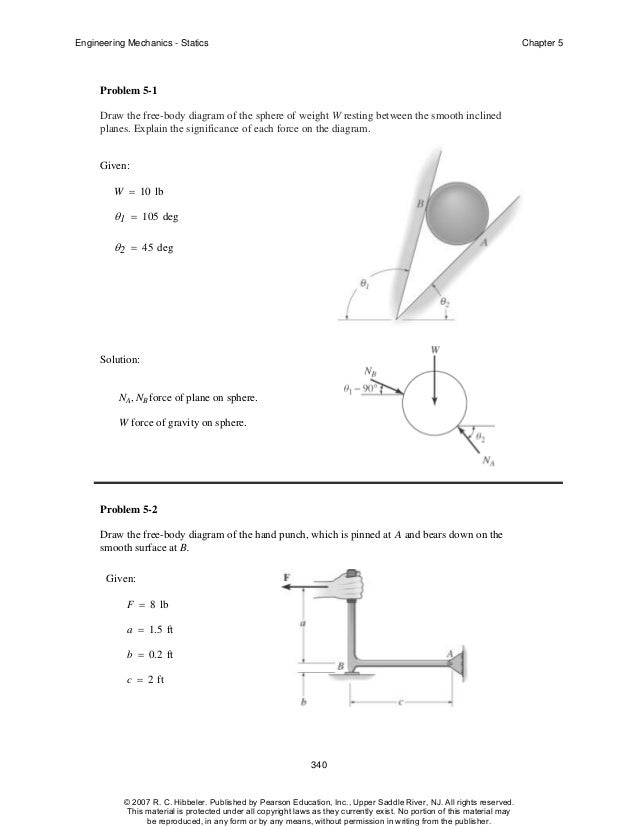
Given: M = 20 gm a = 75 mm b = 200 mm θ = 40 deg Solution: A x , A y , NB force of glass on rod. M(g) N force of gravity on rod. Problem 5-7 Draw the free-body diagram of the "spanner wrench" subjected to the force F. The support at A can be considered a pin, and the surface of contact at B is smooth.
10. We now draw a free-body diagram for a section at A. 45˚ 1500 N AB DA 11. F! y = 0 AB sin 45˚- 1500!F x = 0 = AB cos 45˚- DA 12. Solving simultaneous equations gives AB = 2121 N, DA = 1500 N. 13. We now draw a free-body diagram for a section at D. 45˚ 1500 N 2121 N BD D B C A 4500 N
Draw a freebody diagram for you. Draw the vectors starting at the black dots. The location and orientation of the vectors will be graded. The length of the vectors will not be graded. ANSWER: Ch 4 Supplemental [ Edit ] Overview Summary View Diagnostics View Print View with Answers / LH = = 4.68 N T T

To set up the equilibrium conditions, we draw a free-body diagram and choose the pivot point at the upper hinge, as shown in panel (b) of (Figure). Finally, we solve the equations for the unknown force components and find the forces. Figure 12.17 (a) Geometry and (b) free-body diagram for the door.

Figure 5.32 (a) The free-body diagram for isolated object A. (b) The free-body diagram for isolated object B. Comparing the two drawings, we see that friction acts in the opposite direction in the two figures. Because object A experiences a force that tends to pull it to the right, friction must act to the left. Because object B experiences a component of its weight that pulls it to the left ...
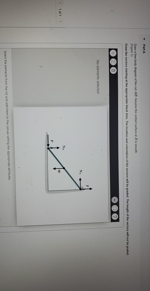
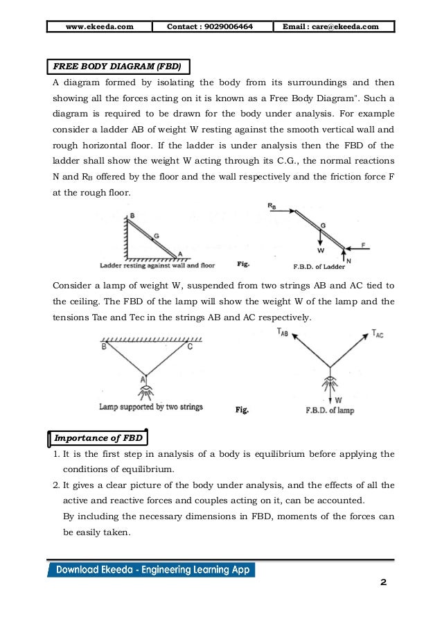
Table 2.2 Free Body Diagrams (FBD) for a Few Typical CasesReacting Bodies FBD required for FBD B a ll W RSm ooth T Smooth Ball R W 600 N 600 N R1 WP Sm ooth Ladder G P R2 T 400 N Block weighing 600 N600 N 600 N R2.13 EQUILIBRIUM OF BODIESA body is said to be in equilibrium when it is at rest or has uniform motion.
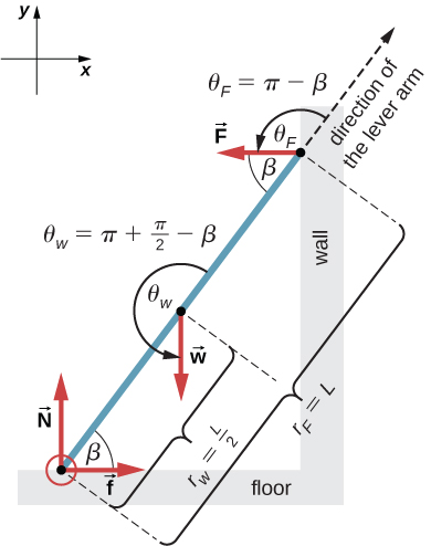
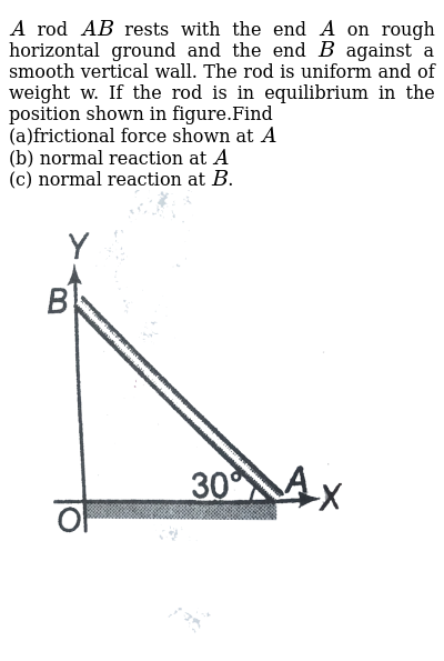
Free-body diagram Assume that only the rollers located at the bottom of the rod are used for support. For each roller at B & C, the reaction is perpendicular to the contact surface. Solution The reaction at A is perpendicular to the wall as the wall is smooth. Equations of Equilibrium + → Σ F x = 0: C y’ sin 30 ο + B y’ sin 30 ο – A ...
Free-Body Diagram: For no motion, reaction at . A must be downward or zero; smallest distance a for no motion corresponds to A = 0. + SM B = 0 200 150 150 50 200 300 0: ( )( ) ( ) ( )( ) ( )N mm N N mm mm- - + +a a A= A a = (200 20000- ) 300
diagram for one object, there is an opposite force vector that appears in the free-body diagram for another object. An example involving two blocks on a table is shown in Fig. 4.1. If a person applies a force F to the left block, then the two free-body diagrams are shown (assume there is no friction from the table).
Draw a free-body diagram of the rod AB.Assume the contact surface at B is smooth.. b) Determine the minimum force P to prevent the 38-kg rod AB from sliding. The contact surface at B is smooth, whereas the coefficient of static friction between the rod and the wall at A is ?s = 0.22.
horizontal surface. A horizontal force Pis applied to the right on the block. The free body diagram of the block is shown in the gure below right. In this free body diagram fand N are the friction and normal components, respectively, of the reaction force of the ground on the block. From this FBD, we have the following equilibrium equations: X F
Assume the contact surface at B is smooth. (Figure 1) Draw the vectors starting at the appropriate black dots. The location and orientation of the vectors will ...
vertical rod by two strings of equal strength and equal length. The strings are very light and do not stretch. The rod is spun with a constant angular acceleration. Which string breaks first? 1. the upper string 2. the lower string 3. they break simultaneously 4. cannot tell without more ...

the internal torque for segment AB varies with x,Fig.b. For segment AB, the maximum internal torque occurs at fixed support A where.Thus, Since ,the critical cross-section is at A.The polar moment of inertia of the rod is .Thus, d = 0.05681 m = 56.81 mm = 57 mm Ans. t allow = Tc J; 2 50(106) = 1800(d>2) pd4>32 J= p a d 2 b 4 = pd4 32 AT ABB max ...
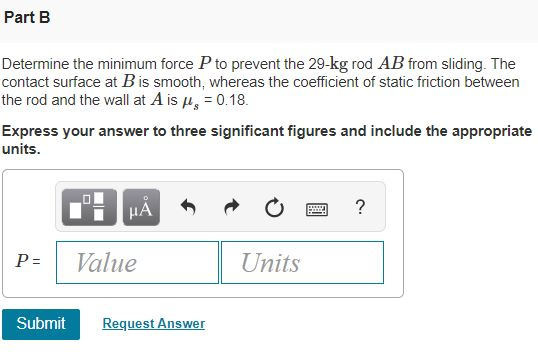
Then determine the minimum force P to prevent the 24-kg rod AB from sliding. The contact surface at B is smooth, whereas the coefficient of static friction ...

velocity and acceleration of cylinder B. Ans. vB = 1.2 m/s up aB = 3 m/s 2 down 23. For the pulley system shown, each of the cables at A and B is given a velocity of 2 m/s in the direction of the arrow. Determine the upward velocity v of the load m. Ans. v = 1.5 m/s If vB = 2 m/s, determine vA such that the mass m does not move. 24.
Question: Draw a free-body diagram of the rod AB. Assume the contact surface at B is smooth. Draw the vectors starting at the appropriate black dots. The location and orientation of the vectors will be graded. The length of the vectors will not be graded. Determine the minimum force P to prevent the 34-kg rod AB from sliding.

B)Determine the minimum force P to prevent the 34-kg rod AB from sliding. The contact surface at B is smooth, whereas the coefficient of static friction between ...

PrObLem 6.1, Fbd OF rOd ab 22. Draw the free-body diagram of the foot lever shown in Figure. The operator applies a vertical force to the pedal so that the spring is stretched 1.5 in. and the force on the link at B is 20 lb. 22 Assume that the 20 lb force is required to cause 1 in. elongation ...
Draw the free-body diagram of member ABCwhich is supported by a smooth collar at A, rocker at B, and short link CD. Explain the significance of each force acting on the diagram. (See Fig. 5–7b.) SOLUTION. The Significance of Each Force: is the smooth collar reaction on member ABC. is the rocker support Breaction on member ABC.
Drawing Free-Body Diagrams. Free-body diagrams are diagrams used to show the relative magnitude and direction of all forces acting upon an object in a given situation. A free-body diagram is a special example of the vector diagrams that were discussed in an earlier unit. These diagrams will be used throughout our study of physics.

9- Draw the free-body diagram(s) ... at B is pinned to the crank AB and is free to slide in a slot cut in member CD. Determine the couple M that must be applied to the crank AB to hold the mechanism in equilibrium when (a) α = 0, (b) α = 30°. 6- A couple M of magnitude 1.5 kN ⋅m is applied ...

5—6. the free-body diagram af the crane boom AB which has a weight of 650 1b and center of gravity at G. The boom is supported by a pin at A and cable BC. The load of 1250 1b is suspended from a cable attached at B. Explain Lhc significance of each force acting on the diagram. (See Dr. Ahmed A. Abu-foul T.A: Eng. Waseem (Younis 30 sithBo COS So
Read Paper. CHAPTER 4 ff PROBLEM 4.1 Two crates, each of mass 350 kg, are placed as shown in the bed of a 1400-kg pickup truck. Determine the reactions at each of the two (a) rear wheels A, (b) front wheels B. SOLUTION Free-Body Diagram: W = (350 kg) (9.81 m/s 2 ) = 3.4335 kN Wt = (1400 kg) (9.81 m/s 2 ) = 13.7340 kN (a) Rear wheels: ΣM B = 0 ...
Draw a kinematic diagram of rod AB and use v B v A ω AB r BA EXAMPLE II EXAMPLE from ENGR 212 at Oregon State University
1. Three point masses lying on a flat frictionless surface are connected by massless rods. Determine the angular acceleration of the body (a) about an axis through point mass A and out of the surface and (b) about an axis through point mass B. Express your answers in terms of F, L, and M.
Draw the free-body diagram of the bar, which has a 75 3mm in. negligible thickness and smooth points of contact at A, B, 30 and C. Explain the significance of each force on the 5 in.mm 125 diagram. (See Fig. 5–7b.)
FREE-BODY DIAGRAMS (Section 5.2) 2. Show all the external forces and couple moments. These typically include: a) applied loads, b) support reactions, and, c) the weight of the body. Idealized model Free-body diagram (FBD) 1. Draw an outlined shape. Imagine the body to be isolated or cut "free" from its constraints and draw its outlined shape.
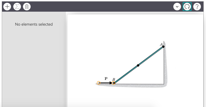
Assume the contact surface at B is smooth. Draw the vectors starting at the appropriate black dots. The location and orientation of the vectors will be graded.


0 Response to "41 draw a free-body diagram of the rod ab. assume the contact surface at b is smooth."
Post a Comment